Special front shaft machining clamp capable of automatically aligning caster angle and inward camber

A special fixture and front axle technology, used in manufacturing tools, metal processing, automatic control devices, etc., can solve the problems of low efficiency of manual line drawing and alignment, and achieve good coplanarity, reliable clamping and high processing efficiency. Effect

Inactive Publication Date: 2015-09-23
ANYANG INST OF TECH
View PDF7 Cites 10 Cited by
  • Summary
  • Abstract
  • Description
  • Claims
  • Application Information

AI Technical Summary

Problems solved by technology

Subsequent processing is based on this coordinate system, and the leaf spring surface after alignment is used as the positioning reference. After processing, the wall thickness of the kingpin hole will not be uneven, too thin or directly become a waste product. After some simple adjustments, the invention can At the same time, it is suitable for aligning different types of front axles with different inclination angles and caster angles; the loading is simple, the automatic alignment is fast, and the operation is simple, which overcomes the shortcomings of low efficiency of manual alignment; the positioning and clamping adopts the hydraulic system, which is fast reliable

Method used


Image

  • Special front shaft machining clamp capable of automatically aligning caster angle and inward camber
  • Special front shaft machining clamp capable of automatically aligning caster angle and inward camber
  • Special front shaft machining clamp capable of automatically aligning caster angle and inward camber

Examples


Embodiment Construction

[0028] The specific implementation manners of the present invention will be described in further detail below in conjunction with the accompanying drawings.

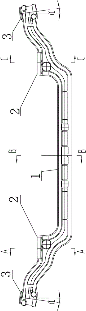
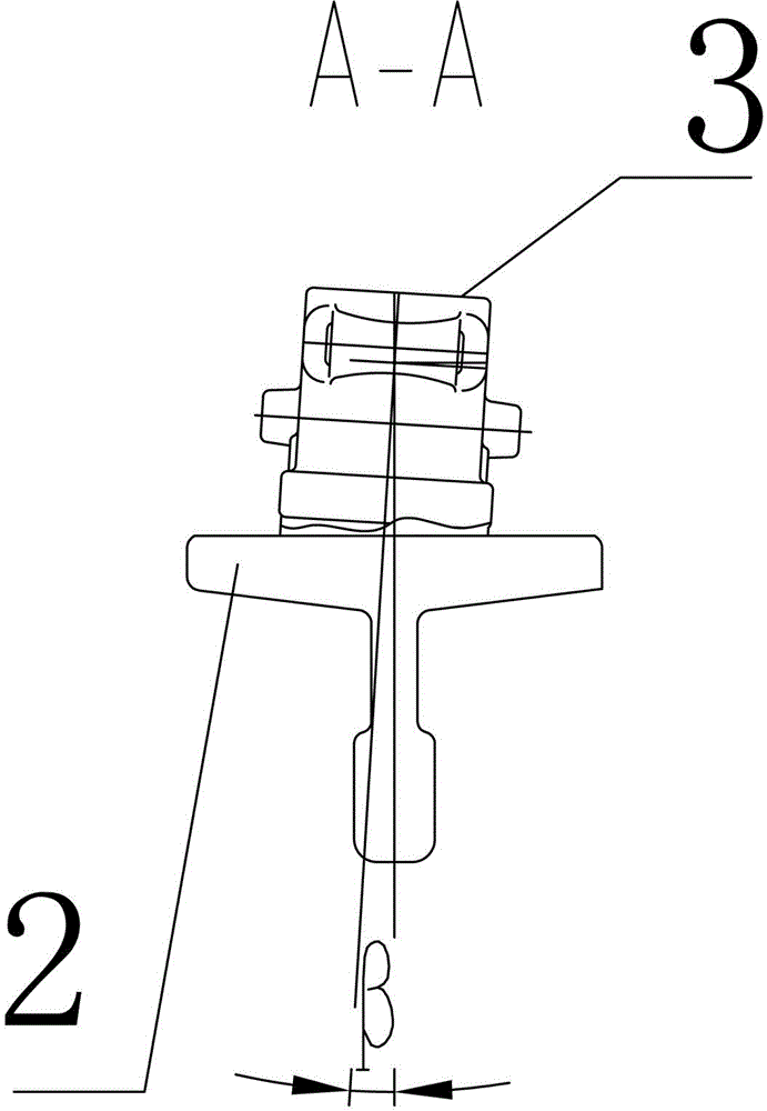
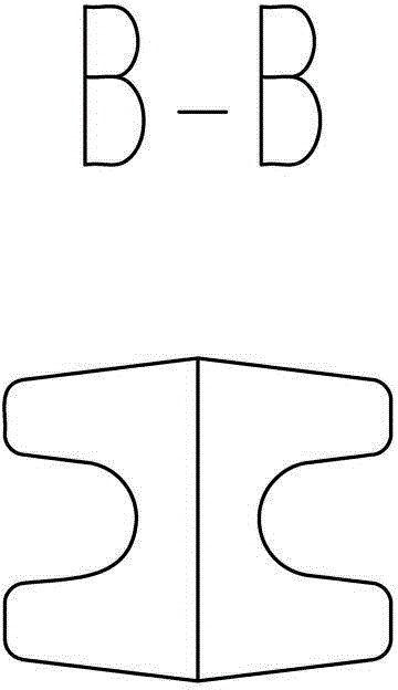
[0029] Depend on Figure 1-Figure 10 Given, including the auxiliary support structure of the I-beam part of the front axle, which can withstand the I-beam part 1 of the front axle to play a supporting role;

[0030] The auxiliary clamping structure of the I-beam part, which can be pressed on the top of the I-beam part 1 of the front axle, and cooperates with the auxiliary support structure of the I-beam part to clamp the I-beam part 1;

[0031] The wedge iron clamping unit placed at the rear of the leaf spring surface 2 of the front axle, the manual thread clamping unit placed at the front of the leaf spring surface 2 of the front axle and the wedge iron self-locking clamping unit to clamp the leaf spring surface of the front axle , the floating support device placed on the lower part of the leaf spring surface 2 of the...


PUM


Abstract

The invention provides a special front shaft machining clamp capable of automatically aligning a caster angle and an inward camber. The caster angle and the inward camber of a workblank are automatically aligned within a certain amount of deformation of the workblank of a front shaft, a front shaft leaf spring face is directly milled after alignment is performed, and a coordinated system using the aligned front shaft leaf spring face as the positioning basis is built and used as the basis during subsequent machining. According to the scheme, the clamp comprises a front shaft H-shaped beam portion auxiliary supporting structure, an H-shaped beam portion auxiliary clamping structure, a clamping H-shaped beam portion, a wedge iron self-locking clamping unit, a manual thread clamping unit, a floating supporting device and an inward camber correcting unit, wherein the front shaft H-shaped beam portion auxiliary supporting structure can abut against the front shaft H-shaped beam portion so as to play a supporting role, the H-shaped beam portion auxiliary clamping structure can compress the portion above the front shaft H-shaped beam portion, the clamping H-shaped beam portion is matched with the H-shaped beam portion auxiliary supporting structure, the wedge iron self-locking clamping unit is arranged at the rear portion of the front shaft leaf spring face, the manual thread clamping unit is arranged at the front portion of the front shaft leaf spring face and used in cooperation with the wedge iron self-locking clamping unit to clamp the front shaft leaf spring face portion, the floating supporting device is arranged at the lower portion of the front shaft leaf spring face, and the inward camber correcting unit is arranged at the position of a front shaft left fist face and used for correcting the front shaft inward camber.

Description

technical field [0001] The invention relates to the field of mechanical processing machine tools. It is a set of special fixtures for processing leaf spring surfaces of automobile front axles, which can be installed on special machine tools or machining centers. front axle. Background technique [0002] Good four-wheel alignment parameters help to improve vehicle handling ability and active safety, and prolong the service life of vehicle suspension and wheels. Four-wheel alignment includes front wheel alignment and rear wheel alignment. The front wheel components are composed of front axle, steering knuckle and hub It consists of three parts. The most important one is the front axle parts, the precision and rigidity of which parts are the key to determine the performance of the front axle assembly. [0003] In order to realize the front wheel camber, toe-in and other parameters in the four-wheel alignment parameters, the front axle parts are designed with inclination (negat...

Claims


Application Information

Patent Timeline
Patent Type & Authority Applications(China)
IPC IPC(8): B23Q3/06B23Q3/10B23Q15/26
CPCB23Q3/064B23Q3/10B23Q3/105B23Q15/26
Inventor 何强王志刚马江虎本杰明孙红英李丽丽张国烨李均张勇
Owner ANYANG INST OF TECH
Why Eureka
Try Eureka