Structure of handgrip and method for fabricating the same

A handle and shell technology, applied in the field of handle structure and manufacture of the handle, can solve the problems of coating peeling, characters or graphics damage, etc., to achieve the effect of having a beautiful appearance

Inactive Publication Date: 2003-12-31
LG ELECTRONICS INC
View PDF0 Cites 11 Cited by
  • Summary
  • Abstract
  • Description
  • Claims
  • Application Information

AI Technical Summary

Problems solved by technology

[0009] An object of the present invention is to provide a novel structure of a handle and a method of making the handle, which solve the problems of peeling off of the coating and damage to engraved or embossed characters or figures, thereby being different from conventional handles and capable of improving The appearance of the handle

Method used


Image

  • Structure of handgrip and method for fabricating the same
  • Structure of handgrip and method for fabricating the same
  • Structure of handgrip and method for fabricating the same

Examples


Embodiment Construction

[0073] Reference will now be made in detail to the preferred embodiments of the invention, examples of which are in Figure 2-33 Examples are shown.

[0074] First, refer to Figure 2-9 The structure of the handle according to the first embodiment of the present invention and its manufacturing method will be described.

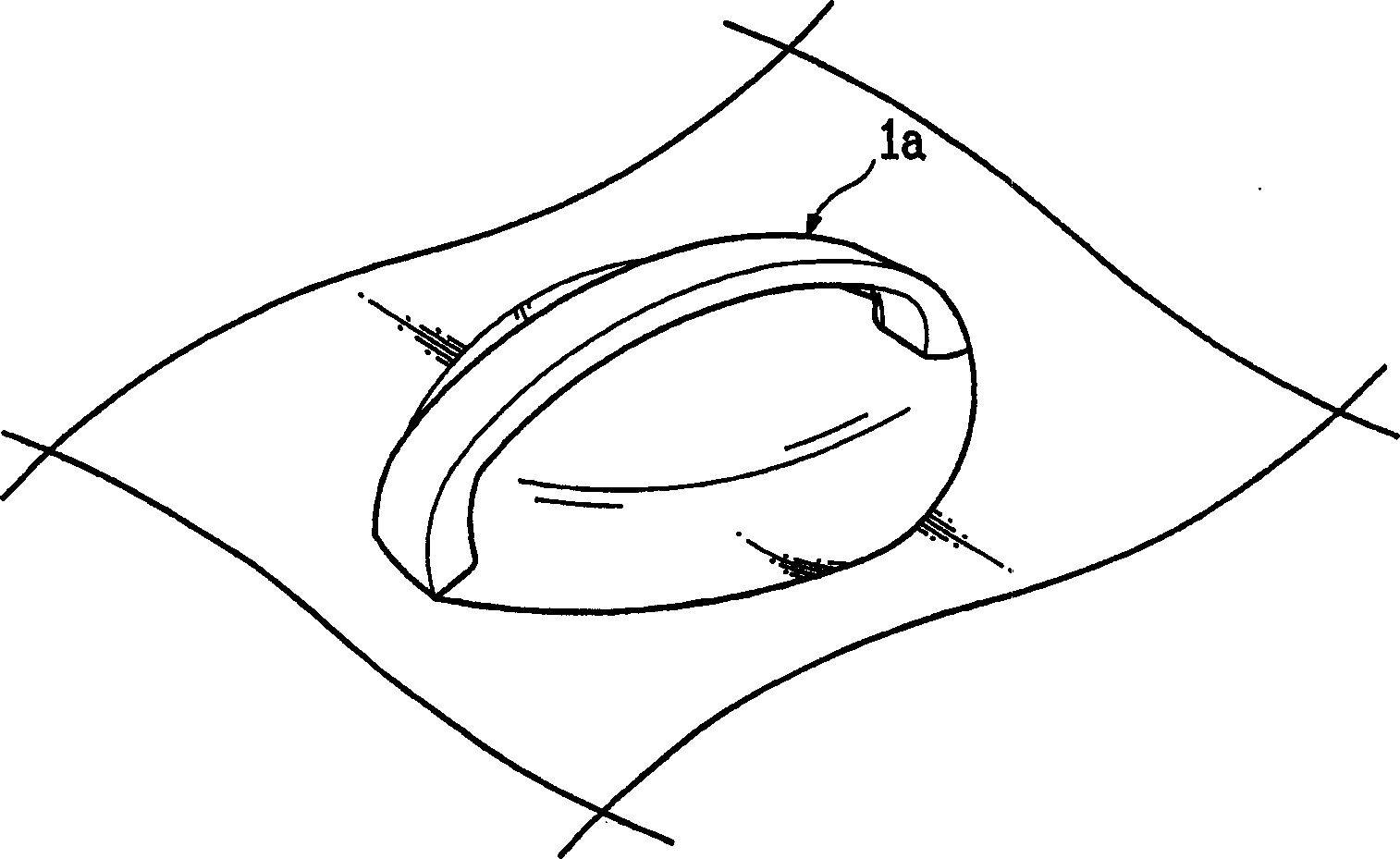
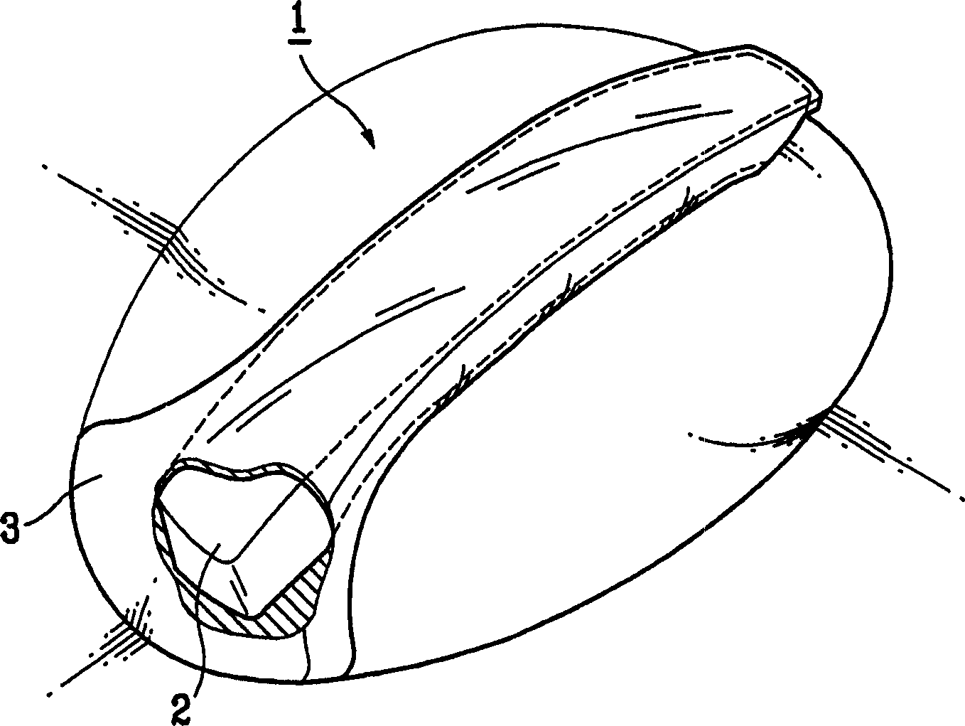
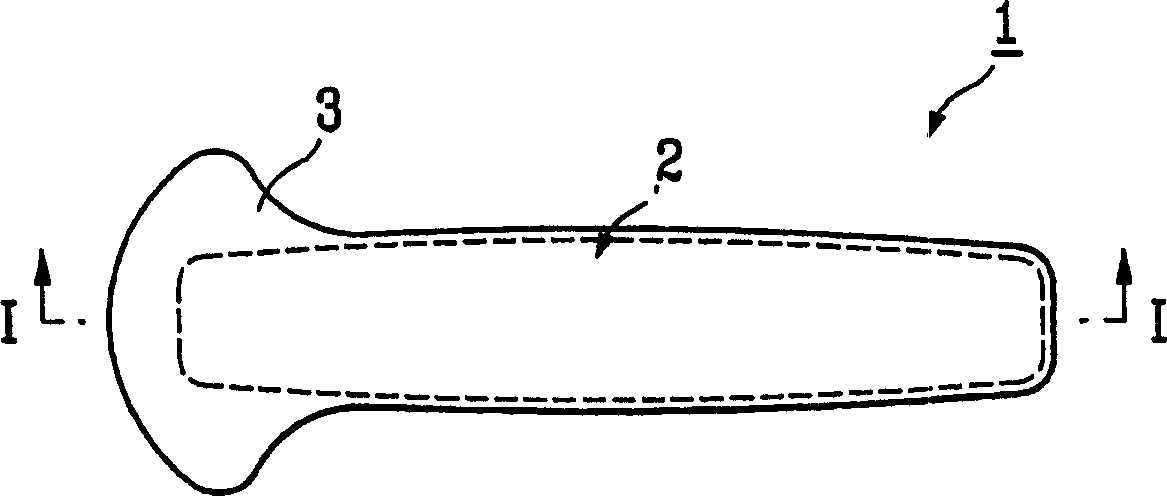
[0075] figure 2 is a perspective view of an application example of a handle structure according to an embodiment of the present invention, image 3 is a top view of the handle according to the first embodiment of the present invention; Figure 4 yes image 3 The bottom view of the handle; Figure 5 is along image 3 A longitudinal sectional view taken along line I-I.

[0076] The handle 1 according to the first embodiment of the invention comprises a colored core 2 and a transparent shell 3 covering the core 2 .

[0077] The core 2 is preferably made in the form of a rod. In the case of a rod-type core, it is preferable that the core 2 has a predeter...


PUM

PropertyMeasurementUnit
melting pointaaaaaaaaaa

Abstract

New form of handgrip for various home appliances, and method for fabricating the same, including a core 2 with decorative color, and a transparent outer shell 3 for enclosing the core 2, thereby solving problems of the present handgrip of peeling off of coating, and damage to carved, or relieved figures, or characters, and providing an outer look distinctive from the present handgrip.

Description

technical field [0001] The present invention relates to a handle structure for various household appliances and a method for manufacturing the handle, in particular to a handle structure suitable for various household appliances, such as laundry rooms, refrigerators, microwave ovens, and car doors, etc. A method of making the handle. Background technique [0002] figure 1 An illustration of a conventional handle, mainly applicable to doors or covers of household appliances. To manufacture this conventional handle, a mold is made with a cavity in the shape of the desired handle, and resin is injected into the cavity to form a handle. Thereafter, in order to obtain a high-grade appearance of the finished handle 1a, its surface is subjected to a coating treatment. [0003] At the same time, in recent years, in addition to the function of the product, the aesthetic feeling of the appearance has become a very important factor of product market demand. Therefore, manufacturers...

Claims


Application Information

Patent Timeline
Patent Type & Authority Applications(China)
IPC IPC(8): E05B1/04B29C45/14B29C45/16B29C45/17B29C45/26B29L31/44B60N3/02E05B1/00F24C7/02F24C15/02F25D23/02
CPCB29C45/1704Y10T16/458B29C45/14819B29C2045/0079B60N3/02Y10T428/23E05B1/0015B29L2031/463B29C45/16E05B1/04B29C45/14065
Inventor 朴硕奎车雄吉金明德
Owner LG ELECTRONICS INC
Why Eureka
Try Eureka