Eureka AIR delivers breakthrough ideas for toughest innovation challenges, trusted by R&D personnel around the world.

Device for securing trim to a seat

a technology for securing seats and trims, applied in the direction of gripping heads, upholstery, manufacturing tools, etc., can solve the problems of inconvenient securing seat trims, inconvenient securing, and inability to meet current demands, so as to facilitate automatic securing of seat trims, ensure the grip of trims, and ensure the appearance of seats

Active Publication Date: 2012-08-21
AUTOMATED SOLUTIONS
View PDF30 Cites 11 Cited by
  • Summary
  • Abstract
  • Description
  • Claims
  • Application Information

AI Technical Summary

Benefits of technology

[0009]An example method of securing trim to a seat cushion includes positioning the seat cushion relative to a plurality of grippers. Each of the grippers has a plurality of prongs in a neutral position. An appropriate portion of the trim is received by the prongs while they are in the neutral position. The prongs are then moved into a closed position where they maintain a firm grip on the trim. The grippers and the trim are then manipulated relative to the seat foam to secure at least a portion of the trim into clips that are fixed to the foam. The prongs of the grippers are then moved into a released position so that the trim, which is now connected with the seat foam, can be handled as desired.
[0010]A machine and process designed according to this invention facilitates automatically securing seat trim to a seat cushion that results in a well-defined seat appearance and provides consistently reliable results.

Problems solved by technology

This approach is relatively labor intensive and time consuming.
Additionally, there are inconsistencies and inaccuracies with this approach because it is very operator dependent.
The hog ring-tying approach often does not meet current demands.
While this technique is generally reliable for providing good seat definition and more automated than the hog ring-tying approach, there are drawbacks.
This at least partially reduces the softness associated with the foam of the seat cushion.
The hardened foam diminishes seat occupant comfort levels.

Method used


Image

  • Device for securing trim to a seat
  • Device for securing trim to a seat
  • Device for securing trim to a seat

Examples


Embodiment Construction

[0022]This invention provides an automated solution to the process of securing trim to a seat cushion in an efficient and reliable manner which provides improved definition and comfort compared to prior techniques. A disclosed example arrangement and process facilitates securing trim to a seat cushion as part of an overall seat assembly process.

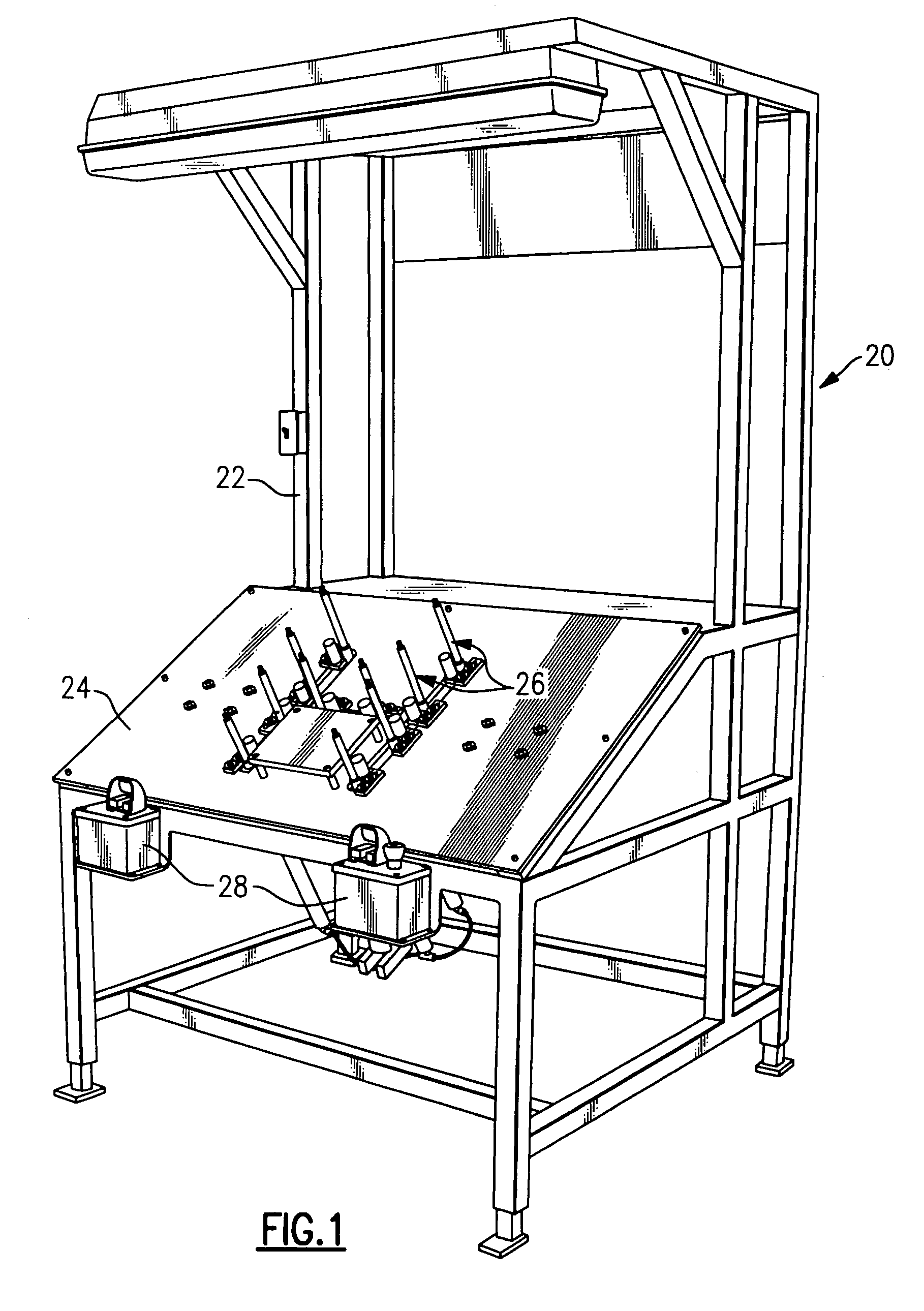
[0023]FIG. 1 diagrammatically illustrates an example machine 20 that is useful for securing trim to a seat cushion. The example machine 20 includes a frame 22 and a work surface 24. A plurality of grippers 26 are arranged on the work surface 24 in a configuration that corresponds to a predetermined pattern based upon a particular seat style, for example. A control 28 is associated with the grippers 26 and allows an operator to control operation of the grippers 26 to facilitate an at least partially automated process for securing trim on a seat cushion.

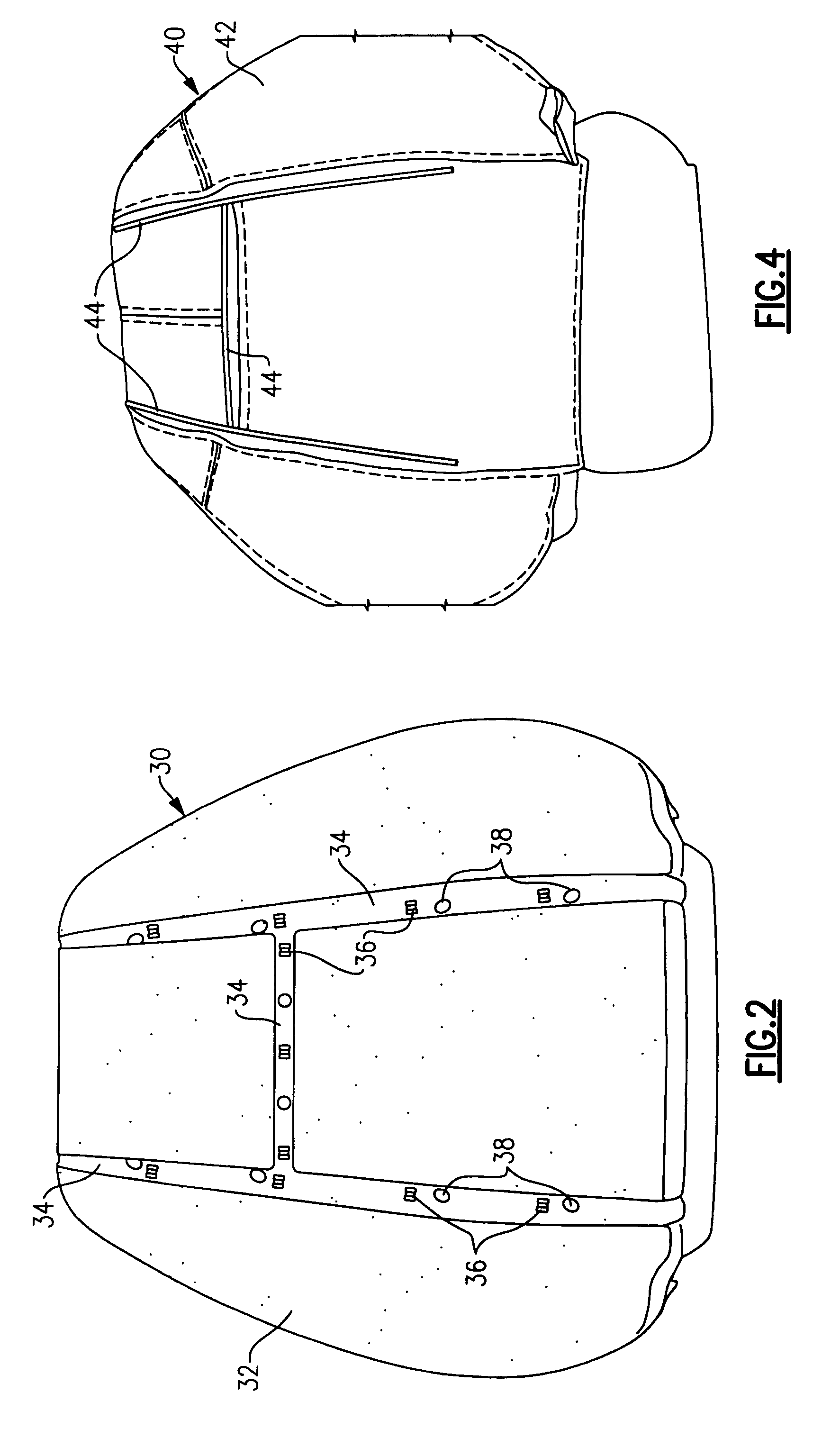
[0024]FIG. 2 diagrammatically shows an example seat cushion 30. This example may be used as ...


PUM

PropertyMeasurementUnit
interior dimensionaaaaaaaaaa
shapeaaaaaaaaaa
timeaaaaaaaaaa

Abstract

A seat assembly machine includes a plurality of grippers useful for securing a piece of trim to a seat cushion. In a disclosed example, each gripper includes a plurality of prongs that are moved between neutral, closed and released positions that each facilitate a different portion of the assembly process. In one example, each gripper includes a sleeve within which the prongs are moveable so that the prongs are manipulated between the neutral, closed and released positions. A disclosed example sleeve includes an interior channel having a contour that manipulates the prongs between the different positions based on the location of the prongs within the sleeve.

Description

CROSS REFERENCE TO RELATED APPLICATIONS[0001]This application claims priority to U.S. Provisional Application No. 60 / 692,934, which was filed on Jun. 22, 2005.BACKGROUND OF THE INVENTION[0002]Seat manufacturing techniques are known for making seats such as those used in automotive vehicles. Typical seats include a cushion having a contour that establishes a shape of the seat. The cushion is supported on a seat frame. A covering such as fabric or leather covers over the foam. The covering is typically referred to as the seat trim. The manner in which a trim cover conforms to the intended shape of the seat, which is typically dictated by the shape of the foam cushion and the supporting seat structure, is commonly referred to as the seat definition. The better that the trim conforms to the foam cushion and the intended seat contour, the better the definition.[0003]There are various known techniques for securing trim onto a seat. One technique includes providing hog rings on the foam an...

Claims


Application Information

Patent Timeline
Patent Type & Authority Patents(United States)
IPC IPC(8): B23Q7/04B68G7/05B68G7/12
CPCB68G7/05B25J15/0028Y10T29/48Y10T29/53961Y10T29/53Y10T29/481Y10T29/53991
Inventor ORMACHEA, RAYMONDBAILEY, ROBERT
Owner AUTOMATED SOLUTIONS
Why Eureka
Eureka Blog
Learn More