Transmission apparatus and reception apparatus

A technology for sending devices and receiving devices, which is applied in the direction of using return channels for error prevention/detection, digital transmission systems, electrical components, etc., and can solve the problems of increasing the amount of temporarily stored data and increasing the buffer capacity of receiving devices, etc.

Inactive Publication Date: 2003-12-31
PANASONIC CORP
View PDF1 Cites 5 Cited by
  • Summary
  • Abstract
  • Description
  • Claims
  • Application Information

AI Technical Summary

Problems solved by technology

[0005] However, the conventional device has a problem that when there is a delay in error detection of a transmitted data block or when there is a delay in retransmitting a data block i

Method used


Image

  • Transmission apparatus and reception apparatus
  • Transmission apparatus and reception apparatus
  • Transmission apparatus and reception apparatus

Examples


Embodiment 1

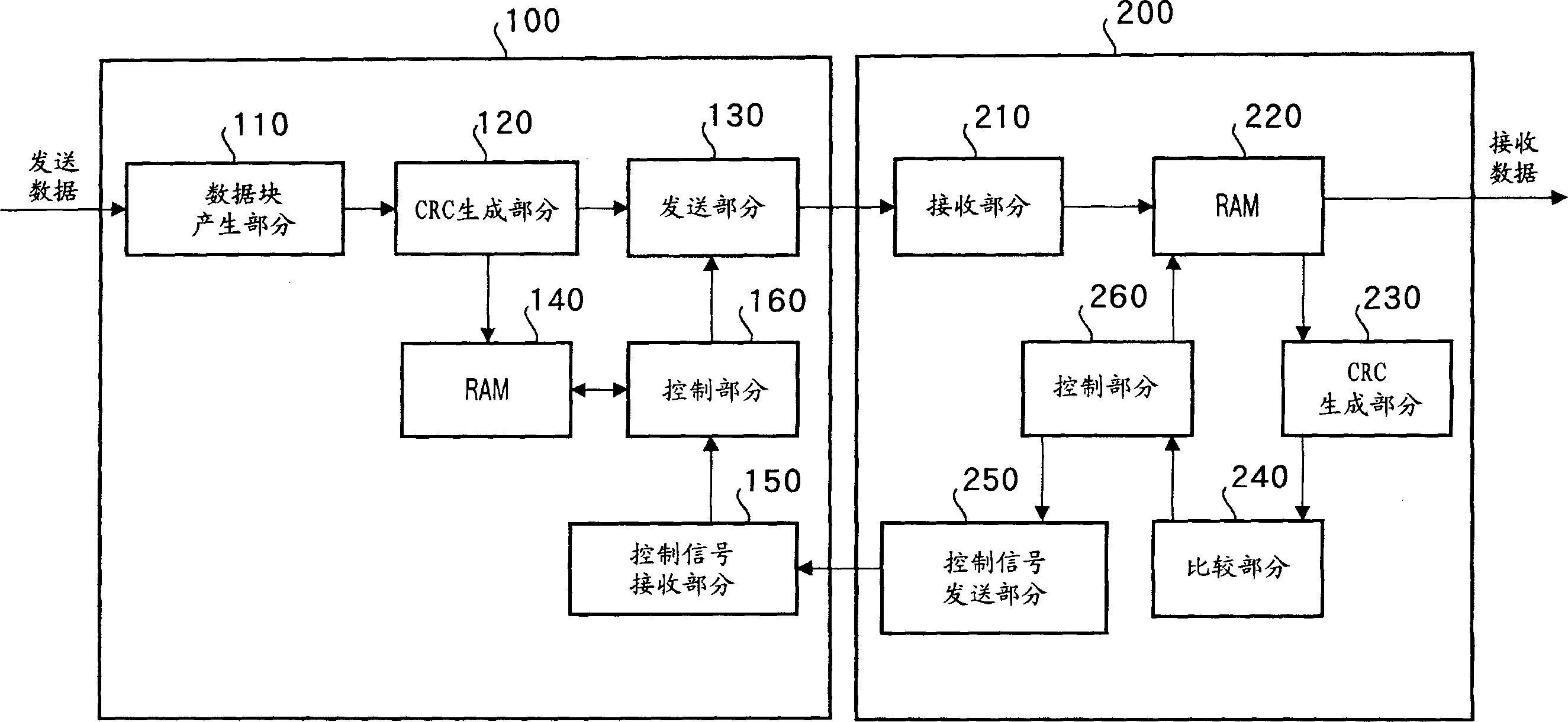
[0027] figure 1 A block diagram showing configurations of a transmitting device and a receiving device according to Embodiment 1 of the present invention. figure 1 The transmission device 100 shown includes: a data block generation section 110, a CRC generation section (error detection code generation section) 120, a transmission section 130, a RAM 140, a control signal reception section (information reception section) 150, and a control section 160.

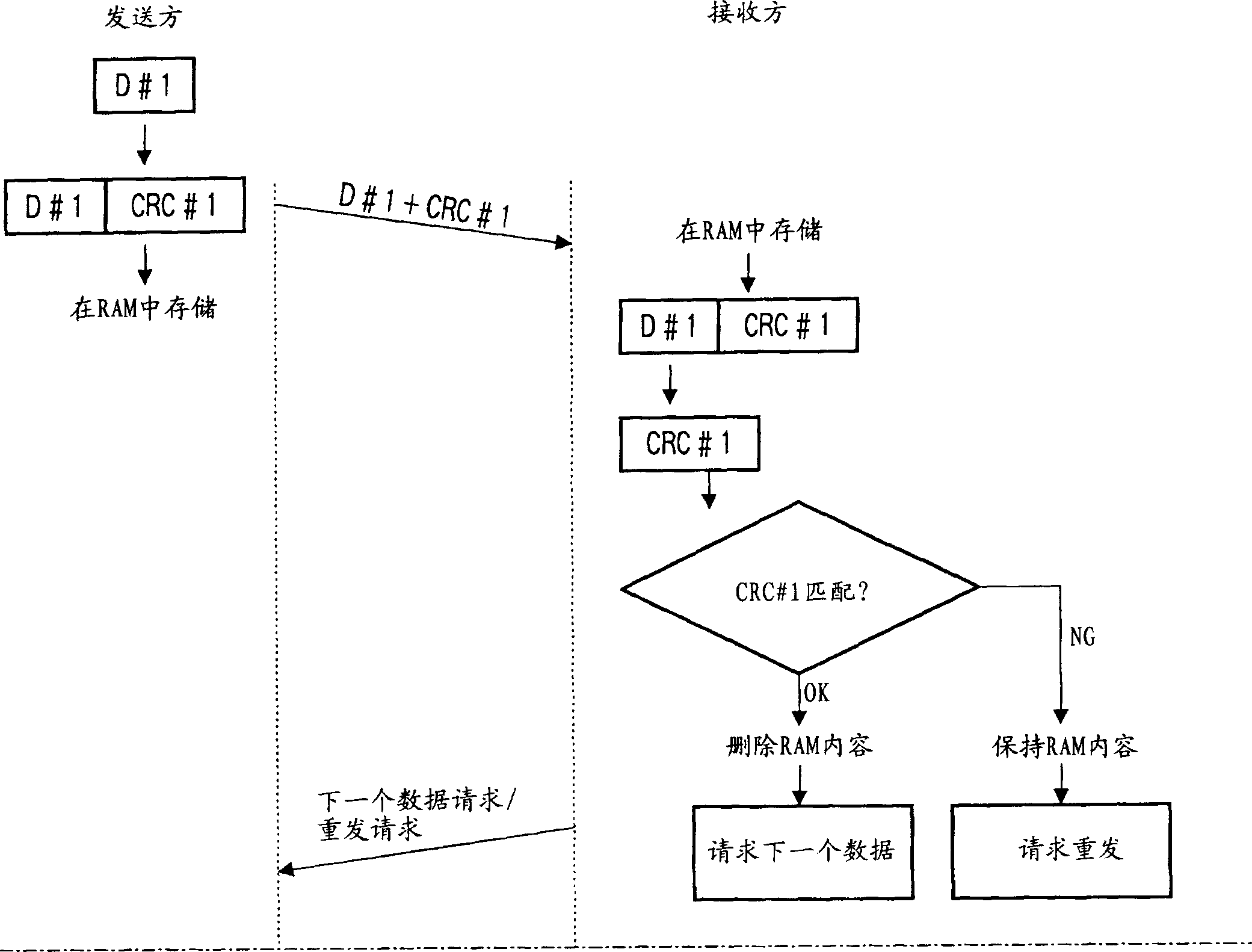
[0028] The data block generation section 110 generates a data block for each transmission unit by dividing the transmission data into blocks. For each data block, the CRC generation section 120 generates a CRC (Cyclic Redundancy Check) code, which is a cyclic redundancy code for error detection, by using a predetermined generator polynomial. For example, in "3GPP Technical Specification TS25.212", a generator polynomial for generating a CRC code is given.

[0029] The transmitting part 130 multiplexes the CRC code generated in...

Embodiment 2

[0046] One feature of Embodiment 2 is that when data is transmitted from the transmitting device to the receiving device, there is no additional CRC code, instead, a CRC code is generated in the receiving device and transmitted to the transmitting device, based on the CRC code first obtained in the transmitting device The comparison of the code with the CRC code transmitted from the receiving device determines the validity / invalidity of the transmitted data.

[0047] image 3 A block diagram showing configurations of a transmitting device and a receiving device according to Embodiment 2 of the present invention. for image 3 neutralize figure 1 The same components are assigned the same reference numerals without further explanation. image 3 The shown sending device 300 includes: a data block generating part 110, a CRC generating part (error detection code generating part) 120, a sending part 330, a RAM 140, a comparison part 360, a CRC receiving part 350 (error detecting c...

Embodiment 3

[0065] A feature of embodiment 3 is: a data block is a group (bundle) of data from top (top) to a given data point (data point), and a plurality of CRC codes are respectively generated corresponding to each of the group of data, In order to specify the location of the data error and retransmit the data corresponding to the location.

[0066] Figure 5 A block diagram showing configurations of a transmitting device and a receiving device according to Embodiment 3 of the present invention. for Figure 5 neutralize image 3 The same components are assigned the same reference numerals without further explanation. Figure 5 The transmission device 500 shown includes: a data block generation part 110, a CRC generation part 120-1~n, a transmission part 130, a RAM 140, a control signal / CRC code reception part 550, a comparison part 560, and a control part 570.

[0067] CRC generating sections 120-1∼n divide the data block into n parts, and generate CRC codes ( Figure 6 The case ...


PUM


Abstract

A transmission apparatus and a reception apparatus for minimizing the buffer size without increasing data amount temporarily stored in the reception apparatus. A data block creation block (110) makes a block out of transmission data on transmission unit basis, thereby creating a data block. A CRC creation block (120) creates a CRC code as an error detection code for each of the data blocks. A transmission block (130) multiplexes the CRC code on the data block so as to be transmitted. An RAM (140) temporarily stores the data block and the CRC code. A control signal reception block (150) receives a control signal indicating the data block transmitted from a reception apparatus (200) and required next. When the control signal received by the control signal reception block (150) requires next data, a control block (160) instructs the transmission block (130) to transmit the next data block. When the control signal requires retransmission, the transmission block (130) is instructed to retransmit the data block and the CRC code stored in the RAM (140).

Description

technical field [0001] The invention relates to a sending device and a receiving device. More particularly, the present invention relates to a transmitting apparatus and a receiving apparatus for detecting or correcting data errors in data communication by using an error detecting code or an error correcting code such as a CRC code. Background technique [0002] Japanese published patent (publication number: 2000-349853) discloses an example of the conventional transmitting device and receiving device of the above type as prior art. [0003] In a conventional data communication with a transmitter and a receiver, the transmitter sends data blocks to the receiver one after the other, wherein the information sequence is divided into blocks and constitutes the transmission data. The receiving device records the received data blocks in the buffer, and at the same time performs error detection for each data block, and when an error is detected, sends a retransmission request for ...

Claims


Application Information

Patent Timeline
IPC IPC(8): H04L1/00H04L1/14H04L1/16H04L1/18H04L29/02H04L29/08
CPCH04L1/14H04L1/0061H04L1/1812H04L1/1835H04L1/1607H04L1/16
Inventor 二木贞树平松胜彦
Owner PANASONIC CORP
Why Eureka
Try Eureka