Mud circulation system

A circulation system and mud technology, applied in wellbore/well components, earthwork drilling, flushing wellbore, etc., can solve problems such as complex operation, complex mechanism, difficult installation and layout, and achieve convenient adjustment and simplification of the mud circulation system Effect

Inactive Publication Date: 2004-01-07
河南石油勘探局南阳石油机械厂
View PDF0 Cites 9 Cited by
  • Summary
  • Abstract
  • Description
  • Claims
  • Application Information

AI Technical Summary

Problems solved by technology

[0003] The mud circulation system of the prior art has a better application effect in the mud circulation of conventional wellbore (hole diameter 7 to 13 inches) or slim hole (hole diameter below 7 inches), that is, in the circulation of high-pressure and small-displacement mud. Good, but when it is applied to the mud circulation in the drilling of large boreholes (wellbore diameter above 13 inches), due to the large displacement, multiple reciprocating piston pumps need to be used in parallel, resulting in complex mechanisms and difficult installation layouts
In addition, the power transmission in the mud circulation system uses the engine to drive the main shaft of the reciprocating piston pump to rotate through mechanical transmission, and the displacement adjustment of the reciprocating piston pump is realized by replacing cylinder liners with different diameters, which is complicated to operate

Method used


Image

  • Mud circulation system
  • Mud circulation system
  • Mud circulation system

Examples


Embodiment 1

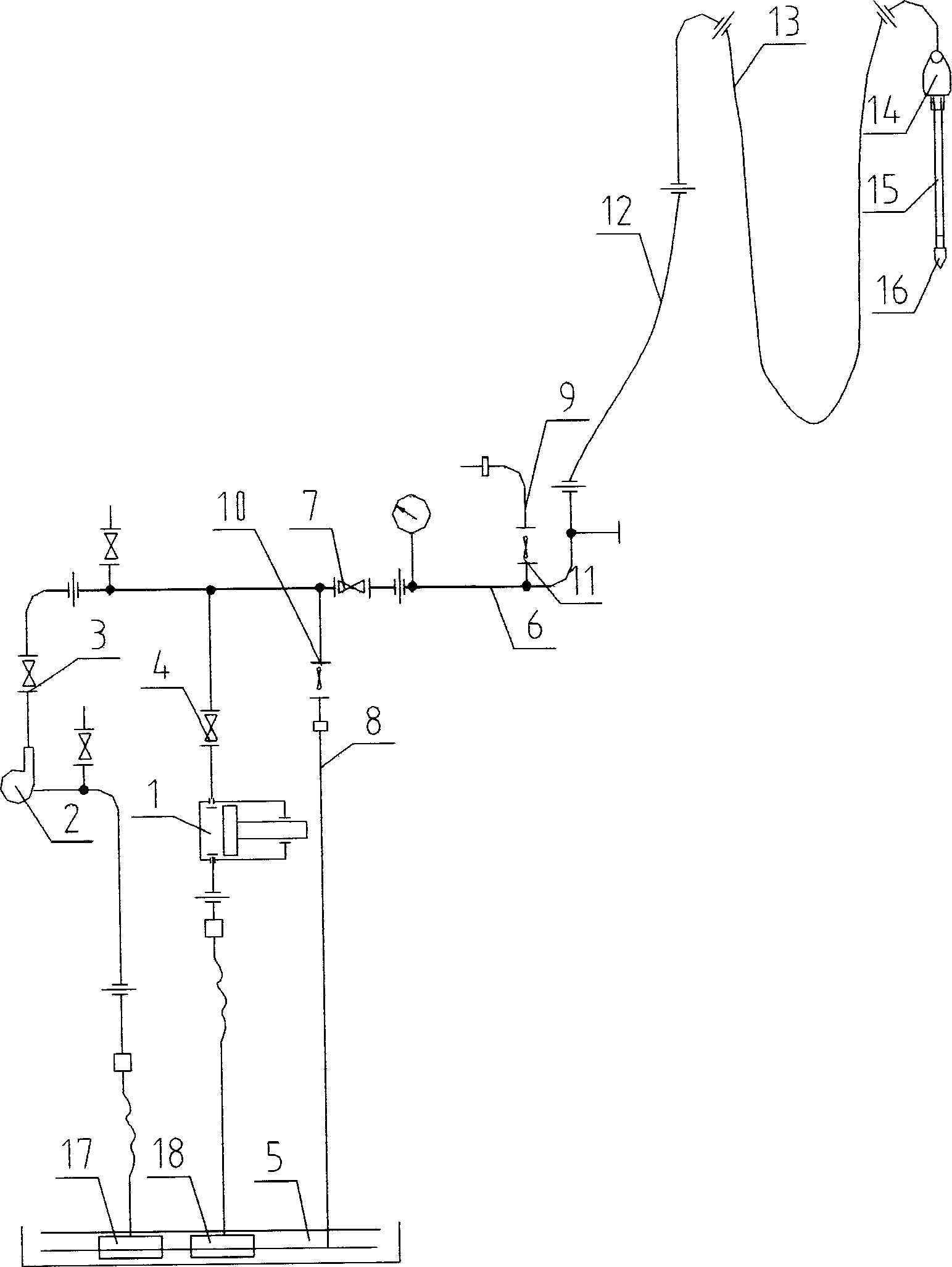
[0017] Such as figure 1 As shown, the centrifugal pump 2 and the reciprocating piston pump 1 are respectively connected between the mud pool 5 and the main line 6 through the valve 3, the valve 4, pipelines, pipe fittings, etc. to form a parallel connection, and the valve 7 is installed on the main line 6, and the main line A return pipeline 8 is also connected between 6 and the mud pool 5, and a grouting pipeline 9 is connected to the main pipeline 6, and a valve 10 and a valve 11 are respectively installed on the return pipeline 8 and the grouting pipeline 9, and the main pipeline 6 and the mud riser 12 , water hose 13, and water tap 14 are connected successively, and the mud that water tap 14 flows out is injected in the well through drill pipe 15, drill bit 16.

[0018] work process:

[0019] When the mud circulation system is used in conventional or slim hole oil and water well drilling, the reciprocating piston pump 1 works and the centrifugal pump 2 does not work becau...

Embodiment 2

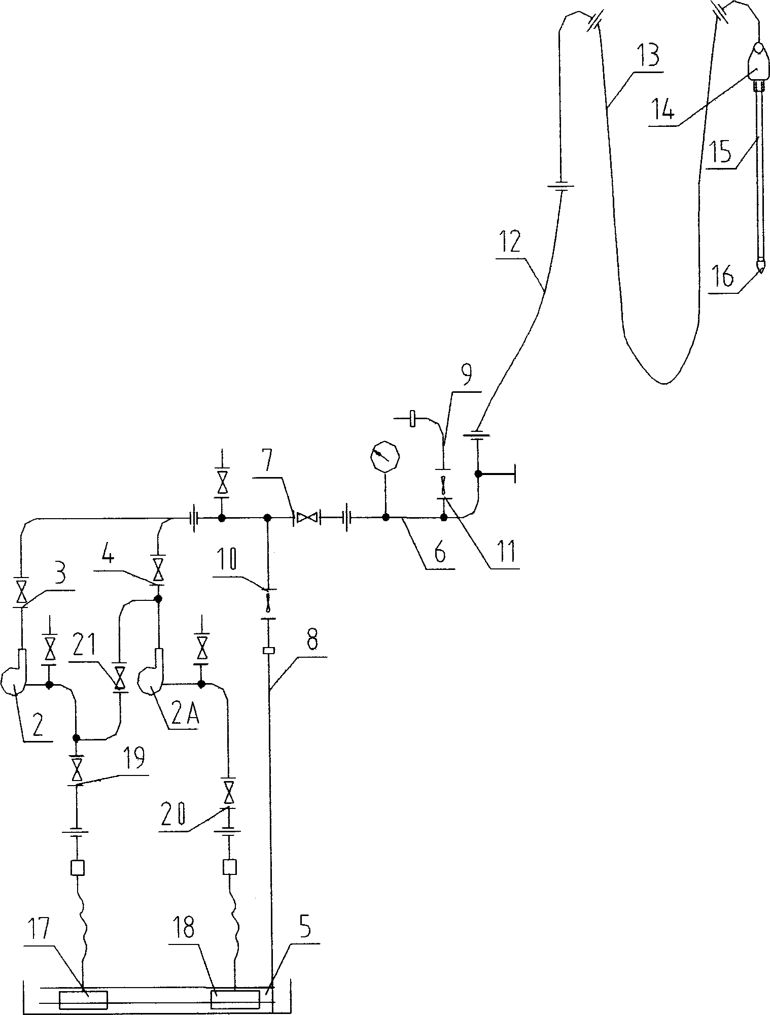
[0024] The reciprocating piston pump 1 in embodiment one is changed into centrifugal pump 2A, as figure 2 As shown, a valve 21 is connected between the inlet of the centrifugal pump 2 and the outlet of the centrifugal pump 2A, and a valve 19 and a valve 20 are respectively installed at the inlets of the centrifugal pump 2 and the centrifugal pump 2A, that is, two centrifugal pumps are connected in series or connected in parallel. When the mud circulation requires large flow and low pressure transportation, the centrifugal pump 2 and the centrifugal pump 2A are connected in parallel, that is, the valve 21 is closed, the valve 3, the valve 4, the valve 19, and the valve 20 are opened, the valve 7 is opened, and the valve 10 and the valve 11 closure. Start centrifugal pump 2, centrifugal pump 2A work, centrifugal pump 2, centrifugal pump 2A suck mud through filter 17, filter 18 respectively, after mud is pressurized, pass main line 6, standpipe 12, water hose 13, water tap 14, ...


PUM


Abstract

The present invention relates to a mud circulation system applicable to mud circulation operation in oil well and water well drilling works. Said system adopts a low-pressure large-displacement centrifugal pump and a high-pressure small-displacement reciprocating piston pump which are parallelly connected between mud pit and circulating main pipeline, and the reciprocating piston pump in the configuration of two drilling pumps can be replaced with centrifugal pump, i.e. two centrifugal pumps can be used, and two connecting modes of series connection of parallel connection of them can be implemented by using control valve opening and closing, and a hydraulic transmission mechanism is used for driving reciprocating piston pump and centrifugal pump.

Description

(1) Technical field [0001] The invention relates to a mud circulation system, which is suitable for mud circulation operation in oil well and water well drilling. (2) Background technology [0002] The mud circulation system is an essential and important part of drilling equipment. During oil well and water well drilling operations, the drilling pump is driven by the input power of the power unit, and the drilling fluid is pumped through the high-pressure manifold on the ground and flows through the standpipe and water hose. The belt, faucet, drill pipe, drill bit, etc. reach the bottom of the well, and carry the cuttings drilled at the bottom of the well to flow through the annular space between the drill pipe and the well wall and return to the ground. Drilling fluid is purified and then pumped to the bottom of the well for repeated circulation, creating a good working environment for the drill bit at the bottom of the well. The mud circulation system of prior art all ado...

Claims


Application Information

Patent Timeline
Patent Type & Authority Applications(China)
IPC IPC(8): E21B21/08
Inventor 李鸿涛尹永晶范淑萍王文尔余德方
Owner 河南石油勘探局南阳石油机械厂
Why Eureka
Try Eureka