Simplified Kalina circulating power generation system

A cycle power generation and generator technology, which is applied in the direction of machines/engines, steam engine devices, mechanical equipment, etc., can solve the problems of lack of power generation system, complexity, etc., and achieve the effect of simplifying the cycle system and reducing the work intensity

Inactive Publication Date: 2020-05-01
DONGGUAN UNIV OF TECH
View PDF0 Cites 0 Cited by
  • Summary
  • Abstract
  • Description
  • Claims
  • Application Information

AI Technical Summary

Problems solved by technology

However, the existing Karina cycle system is relatively complicated, and there is still a lack of a more environmentally friendly power generation system based on the Karina cycle

Method used


Image

  • Simplified Kalina circulating power generation system

Examples


Embodiment 1

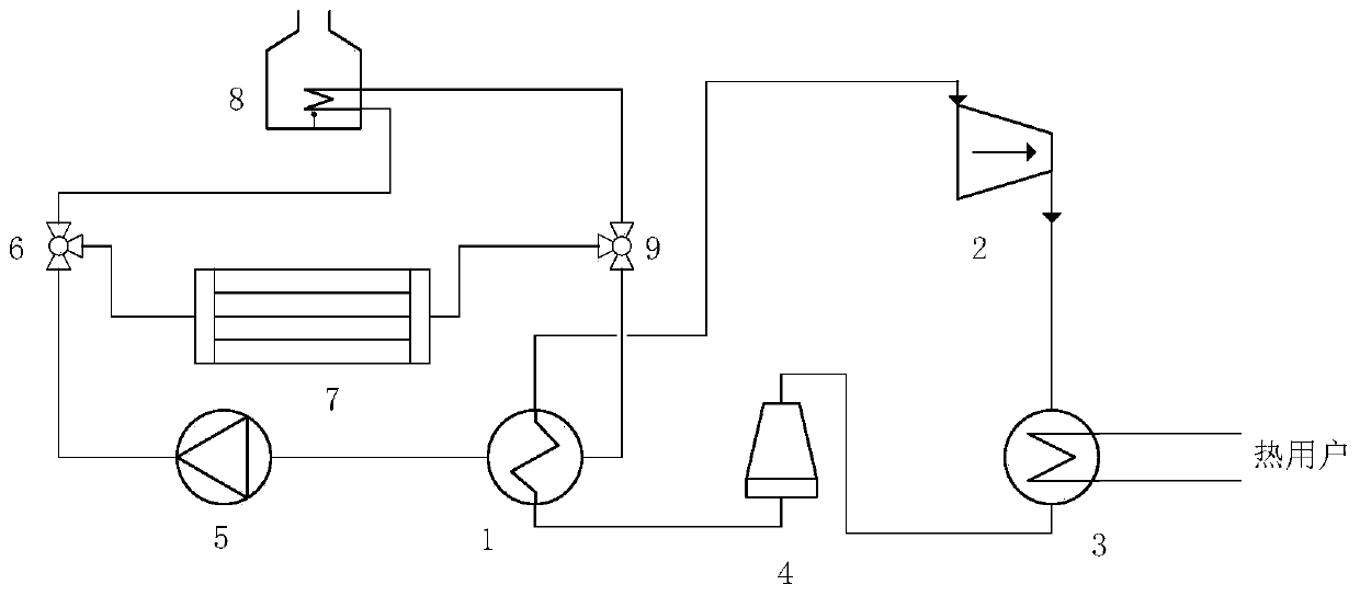
[0029] A simplified Kalina cycle power generation system, such as figure 1 As shown, it includes generator 1, steam turbine generator 2, absorber 3, condenser 4, liquid pump 5, first three-way regulating valve 6, solar heater 7, biomass combustion heater 8, second three-way Regulating valve 9.

[0030] The generator 1 includes a working medium channel and a heating channel, the outlet of the working medium channel is connected with the inlet of the steam turbine generator 2, the outlet of the steam turbine generator 2 is connected with the steam inlet of the absorber 3, and the steam outlet of the absorber 3 is connected with the condenser The inlet of the condenser 4 is connected, and the outlet of the condenser 4 is connected with the inlet of the working medium channel. So far, the working fluid circulation channel is formed.

[0031] The outlet of the heating channel of the generator 1 communicates with the inlet of the liquid pump 5, the outlet of the liquid pump 5 comm...


PUM


Abstract

The invention discloses a simplified Kalina circulating power generation system comprising a generator, a steam turbine generator, an absorber, a condenser, a liquid pump, a first three-way regulatingvalve, a solar heater, a biomass combustion heater and a second three-way regulating valve. According to the simplified Kalina circulating power generation system, the Kalina circulating system is simplified, ammonia water is adopted as the working medium of Kalina circulating, and the working intensity of the solar heater and a biomass heating furnace can be effectively lowered. Moreover, the simplified Kalina circulating power generation system utilizes renewable solar energy and biomass energy to operate and generate electricity, low carbon and environmental protection are achieved, and the adjustment of China's energy structure is facilitated.

Description

technical field [0001] The invention relates to the technical field of power generation systems, and more particularly, relates to a simplified Kalina cycle power generation system. Background technique [0002] With the continuous development of our country's economy, the existing power generation system can no longer meet the growing material and cultural needs of our country. For this reason, our country has established many large-capacity power generation equipment, among which thermal power generation is the most famous. Nowadays, thermal power generation has existed in our country for decades, and the current situation that non-renewable coal is used as the main energy source has formed. It is urgent to develop a new power generation system and improve the existing energy structure. [0003] In today's increasingly severe energy situation, the recovery and utilization of medium and low temperature waste heat resources has attracted more and more attention, and the Kari...

Claims


Application Information

Patent Timeline
IPC IPC(8): F01K11/02F01K25/10
CPCF01K11/02F01K25/106
Inventor 胡冰
Owner DONGGUAN UNIV OF TECH
Why Eureka
Try Eureka