Supercharge Your Innovation With Domain-Expert AI Agents!

Electrical wire fixing equipment for micro-wave oven

A technology for fixing devices and power cords, which is applied in the field of fixing devices for power cords of microwave ovens. It can solve problems such as damage to shell parts and inability to remove grounding wires, and achieve the effects of easy maintenance and convenient operation.

Inactive Publication Date: 2004-01-14
LG ELECTRONICS (TIANJIN) APPLIANCES CO LTD
View PDF0 Cites 5 Cited by
  • Summary
  • Abstract
  • Description
  • Claims
  • Application Information

AI Technical Summary

Problems solved by technology

But, there is following problem in this microwave oven of prior art, promptly because one end of power supply cord 20 is connected with the electronic component in the electric storage room 5, and the other end is connected with external power supply, and passes wire groove 17, if want to disassemble To remove the power cord 20, the casing 30 must be removed first, because the casing 30 has enclosed the grounding piece 18, so the grounding wire 23 mounted on the grounding piece 18 cannot be removed.
Moreover, the parts on the housing 30 may be damaged during the process of removing the housing 30 from the cavity 1 and removing the power cord 20.

Method used


Image

  • Electrical wire fixing equipment for micro-wave oven
  • Electrical wire fixing equipment for micro-wave oven
  • Electrical wire fixing equipment for micro-wave oven

Examples


Embodiment Construction

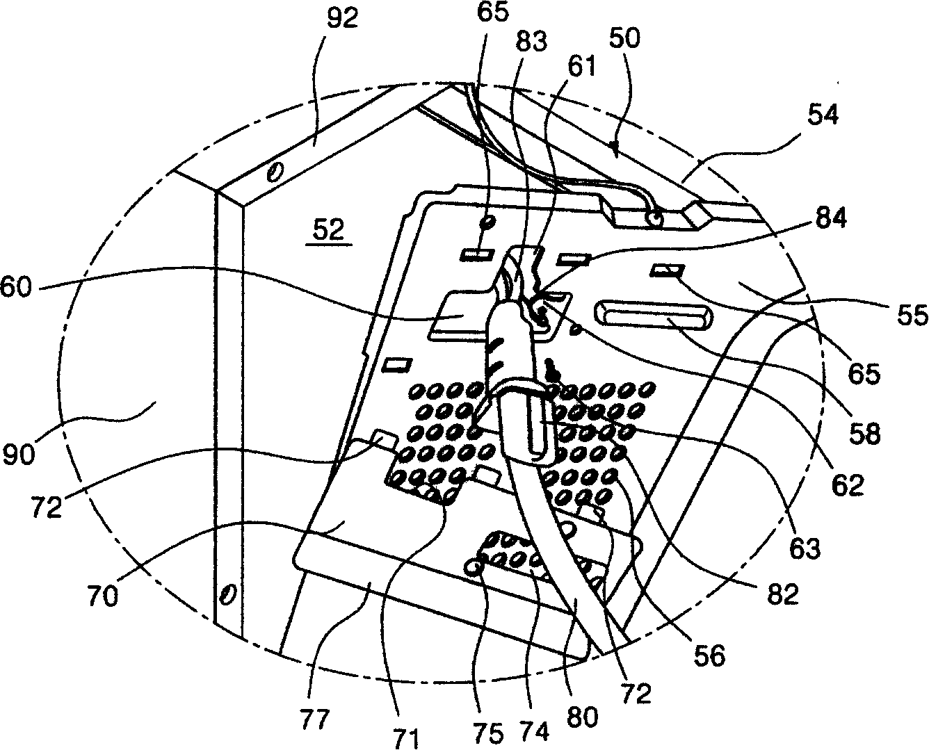
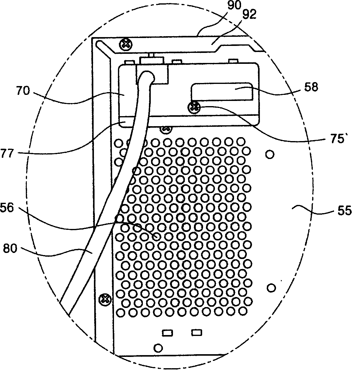
[0014] Such as figure 2 , image 3 As shown, the back panel 55 is the back side of the cavity 50, and a storage room 52 is arranged inside one end thereof. The cavity is provided with an upper panel 54 as the top surface of the cooking chamber. The back panel 55 is provided with a ventilation hole 56 for introducing outside air into the electric storage compartment 52 . A rib 58 protruding outward is provided on the back panel 55 at the upper end side of the vent hole 56 . The rib 58 has the function of positioning the power cord cover while ensuring the strength of the back panel 55 . On the back panel 55 on the upper part of the ventilation hole 56, a rectangular power cord through hole 60 through which the power cord can pass is also provided. The upper part of the power line through hole 60 is provided with a quadrangular stopper mounting part 61 connected thereto. One side of the power line through hole 60 is provided with a ground piece 62 , which is a part of the ...


PUM


Abstract

The present invention discloses a power cord fixing apparatus for the microwave oven, comprising a back panel forming the back of the chamber inner electricity storage chamber for arranging the power cord through-hole, a ground strip arrange on one side of the power cord through-hole on the back panel and integrated with the back panel in connection with the grounding wire, power cord penetrating the power cord through hole and power cord cap for covering the power cord through-hole and mounted on the back panel for fixing the power cord. The apparatus by the invention can facilitate the operation and maintenance for the power cord.

Description

technical field [0001] The invention relates to a power cord fixing device for a microwave oven, in particular to a power cord fixing device for a microwave oven which can facilitate installation and removal of the power cord. Background technique [0002] figure 1 It is an exploded perspective view of the main structure of a microwave oven in the prior art. Such as figure 1 As shown, one side of the cavity 1 is provided with a cooking chamber 3 that can heat food, and the other side is provided with a storage room 5 that is equipped with electronic components that can provide microwaves to the cooking chamber 3 . The front of cavity 1 is provided with front panel 6, and the back is provided with back panel 7, and upper panel 8 constitutes the top of cooking chamber 3, and lower panel 9 then constitutes the two sides and the bottom surface of cooking chamber 3. A magnetron 10 is provided in the electric storage room 5 , and a cooling fan 11 that can cool electrical compon...

Claims


Application Information

Patent Timeline
IPC IPC(8): F24C7/02
CPCH05B6/6426
Inventor 李德吉
Owner LG ELECTRONICS (TIANJIN) APPLIANCES CO LTD
Features
  • R&D
  • Intellectual Property
  • Life Sciences
  • Materials
  • Tech Scout
  • Unparalleled Data Quality
  • Higher Quality Content
  • 60% Fewer Hallucinations
Learn More