Liquid atomizer

A liquid atomization and liquid technology, which is applied in liquid injection devices, injection devices, atomizers for treatment, etc., can solve the problems of stable quantitative spray, unsatisfactory, unstable atomization, etc., to improve convenience and stability. The effect of liquid delivery

Inactive Publication Date: 2004-01-14
OMRON HEALTHCARE CO LTD
View PDF2 Cites 13 Cited by
  • Summary
  • Abstract
  • Description
  • Claims
  • Application Information

AI Technical Summary

Problems solved by technology

However, in fact, the degree of inclination when the device is used, vibration from the outside, the residual liquid in the liquid storage part, etc. are affected, and the supply amount to the atomization part is not constant, and the

Method used


Image

  • Liquid atomizer
  • Liquid atomizer
  • Liquid atomizer

Examples


Embodiment Construction

[0085] Hereinafter, the present invention will be described in more detail based on embodiments.

[0086] (Embodiment 1)

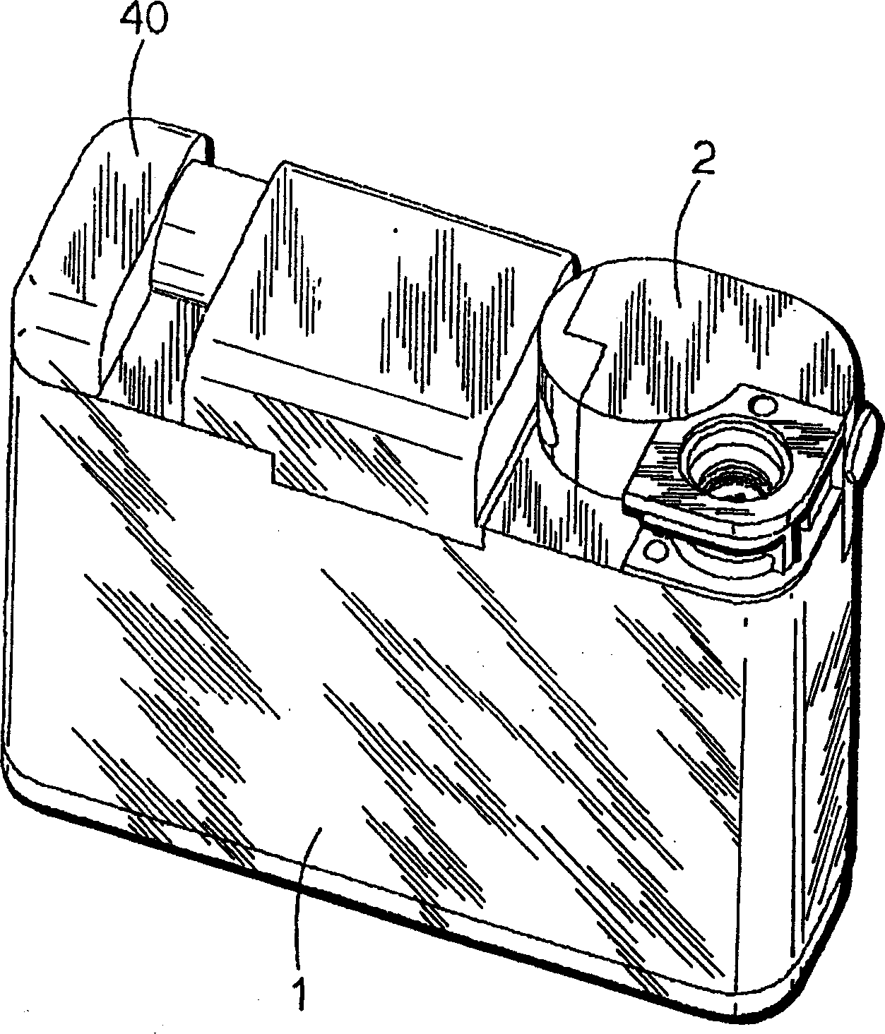
[0087] figure 1 A perspective view showing the appearance of the liquid atomizing device of the first embodiment. The liquid atomizing device is composed of a main body 1 and a liquid supply assembly 2, and the main body 1 has a battery housing portion 5 therein (refer to image 3 ) and the circuit part, etc., the liquid supply assembly 2 is detachably mounted on the main body part 1 .

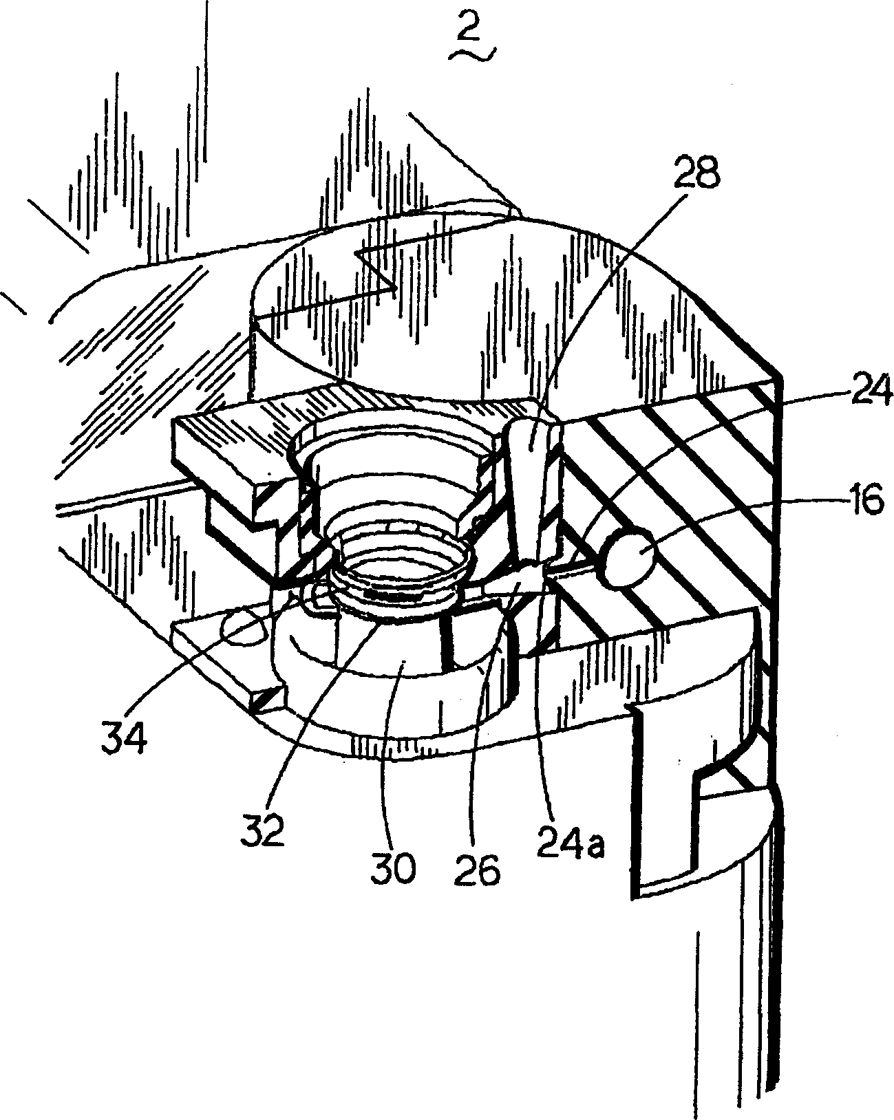
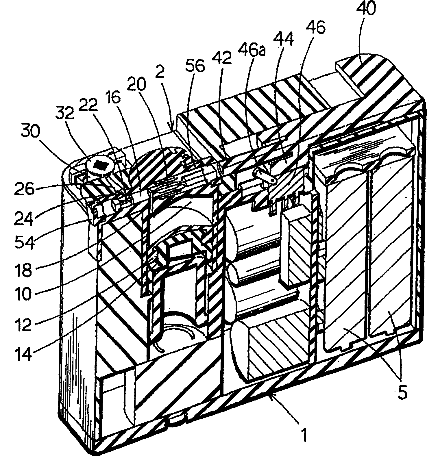
[0088] In a partially cutaway perspective view showing the liquid supply assembly 2 figure 2 and a longitudinal section showing the interior of the device image 3 In the device, a primary liquid storage part 10 for storing the liquid (medicine liquid) to be atomized is disposed inside the device, and a movable member 12 that can move up and down is installed in a liquid-tight manner at the bottom of the primary liquid storage part 10, and the movable member 12 doubles...


PUM


Abstract

A chemical stored in a primary liquid storage part (10) for storing the atomized chemical is filled by a specified amount to a secondary liquid storage part (16) through a liquid feed passage (18), a piston (20) is pushed by an operating rod (42) to turn on a power supply switch (46) when a liquid supply button (40) is slid to the left side, a valve (22) is moved leftward to open a liquid feed passage (24) as the chemical in the secondary liquid storage part (16) is pushed when the piston (20) is moved leftward, and the specified amount of chemical in the secondary liquid storage part (16) is fed to the atomizing part formed of a horn vibrator (30) and a mesh member (32) through the liquid feed passage (24) and a guide groove (26) and atomized there, whereby the atomization can be stabilized by making constant the liquid amount fed to the atomizing part at a low cost.

Description

technical field [0001] The present invention relates to a liquid atomizing device having a liquid feeding mechanism capable of stably supplying liquid in a certain amount each time. Background technique [0002] For example, conventional portable ultrasonic liquid atomizing devices generally have a liquid storage portion that stores liquid (medicine), a vibration source (for example, an ultrasonic horn vibrator) that supplies the liquid in the liquid storage portion to the distal end portion, and is arranged in contact with the liquid storage portion. The mesh member having a plurality of fine holes on the end face of the front end portion of the vibration source atomizes the liquid in the liquid storage portion by the vibration action of the vibration source and the mesh member. [0003] That is, the liquid in the liquid storage part enters the gap between the mesh member and the front end of the vibration source, and the vibration action of the end surface of the mesh memb...

Claims


Application Information

Patent Timeline
IPC IPC(8): A61M11/00A61M15/00B05B17/06
CPCA61M15/008B05B17/0676A61M15/0085A61M11/007A61M15/0065A61M2011/007A61M2015/008B05B17/0607A61M11/005B05B17/0623A61M11/00
Inventor 寺田隆雄朝井庆荒井真人西村寿太郎田畑信田中伸哉伊藤伸一
Owner OMRON HEALTHCARE CO LTD
Why Eureka
Try Eureka