Flow control of extruder

A technology of compressors and expanders, which is applied to compressors using turbines, irreversible cycle compressors, refrigerators, etc., and can solve problems such as waste of power

Inactive Publication Date: 2004-01-21
CARRIER CORP
View PDF0 Cites 3 Cited by
  • Summary
  • Abstract
  • Description
  • Claims
  • Application Information

AI Technical Summary

Problems solved by technology

Pre-throttling wastes power because the energy is not being used

Method used


Image

  • Flow control of extruder
  • Flow control of extruder
  • Flow control of extruder

Examples


Embodiment Construction

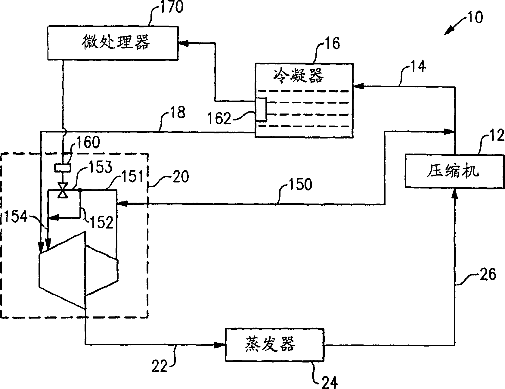
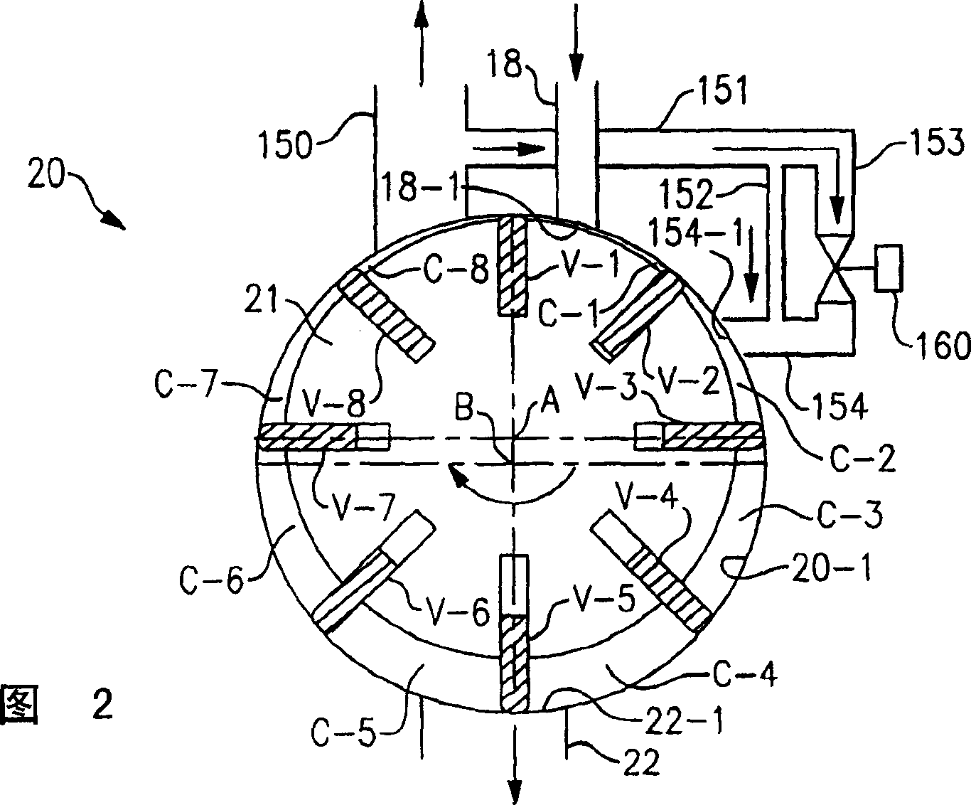
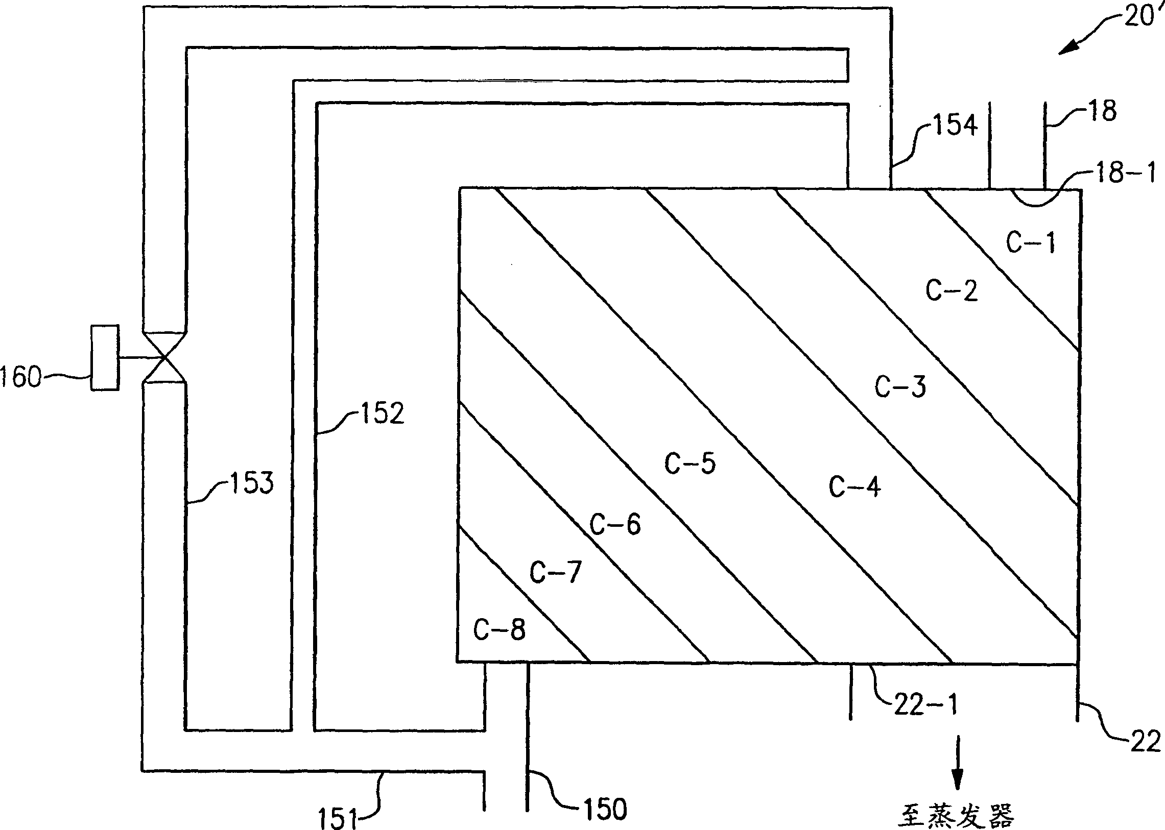
[0015] exist figure 1 , reference numeral 10 generally denotes a refrigeration system or an air conditioning system. The system 10 comprises in sequence, starting from the compressor 12, a discharge line 14, a condenser 16, a line 18, an expansion device in the form of an extractor 20, a line 22, an evaporator 24 and a suction line 26, so that the complete the loop. Referring to Figure 2, the extruder 20 shown is a rotating vane device that nominally uses half of each revolution as an expander and half of each revolution as a compressor, so the extruder 20 is a two-stage device that is effectively balanced in terms of loads and the like. As shown, the extruder 20 has a rotor 21 about an axis of rotation A and eight symmetrically circumferentially spaced vanes, designated V-1 to V-8, respectively. Vanes V-1 to V-8 seal against the cylinder wall defined by cylinder 20-1 due to centrifugal force, or are spring biased into contact with the cylinder wall if necessary or desired....


PUM


Abstract

The saturated or supercooled liquid is supplied to an expander of an expressor. Starting just prior to the end of an inlet process or just after completion of the inlet process, high pressure vapor from an expressor compressor discharge is supplied to a cavity defining a trapped volume undergoing expansion.

Description

technical field [0001] The invention relates to an extruder of a closed refrigeration system. Background technique [0002] All hermetic refrigeration systems sequentially comprise a compressor, a condenser, an expansion device, and an evaporator. Expansion devices include fixed orifices, capillary tubes, thermal expansion valves, electronic expansion valves, turbines, and expander-compressors or extruders. In each expansion device, as the high-pressure liquid refrigerant undergoes a pressure drop, the high-pressure liquid refrigerant undergoes a flash wherein at least a portion of the liquid refrigerant becomes a vapor, resulting in an increase in specific volume. In the extruder, the increase in volume is used to power the fitted compressor, which delivers high pressure refrigerant vapor to the discharge of the system compressor, thereby increasing system capacity. Because the compression process that occurs in the extruder is not powered by an electric motor, but by the...

Claims


Application Information

Patent Timeline
Patent Type & Authority Applications(China)
IPC IPC(8): F25B9/06F04C18/16F04C18/344F04C28/06F04C29/00F25B1/04F25B11/02
CPCF04C28/06F04C18/3442F25B2500/26F25B11/02F25B2700/04F04C18/16F25B1/04F04C29/0007F25B2600/2501F25B2400/14F25B2600/026F25B9/06
Inventor 汤炎J·J·布拉斯兹
Owner CARRIER CORP
Why Eureka
Try Eureka