Optical sliding mouse possessing rolling ball

An optical and mouse technology, applied in the input/output process of data processing, instruments, electrical digital data processing, etc., can solve the problems of the optical recognition unit 42 being unable to receive continuous pictures, poor work, and wrong indicator signals of the optical sliding mouse 20.

Inactive Publication Date: 2004-02-18
PRIMAX ELECTRONICS LTD
View PDF0 Cites 1 Cited by
  • Summary
  • Abstract
  • Description
  • Claims
  • Application Information

AI Technical Summary

Problems solved by technology

[0007] Although the above-mentioned optical sliding mouse 20 has indeed solved the problem of bad work caused by dust accumulation on the traditional mechanical sliding mouse 10
But when the plane 26 that the optical sliding mouse 20 touches and operates is a material such as a glass or a special color

Method used


Image

  • Optical sliding mouse possessing rolling ball
  • Optical sliding mouse possessing rolling ball
  • Optical sliding mouse possessing rolling ball

Examples


Embodiment Construction

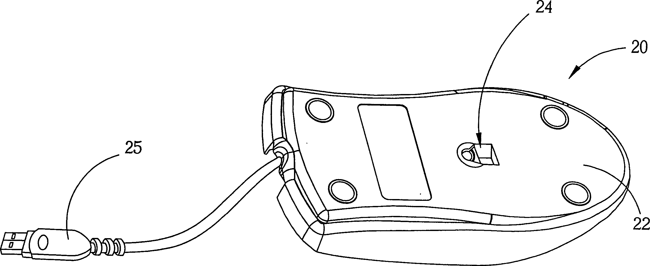
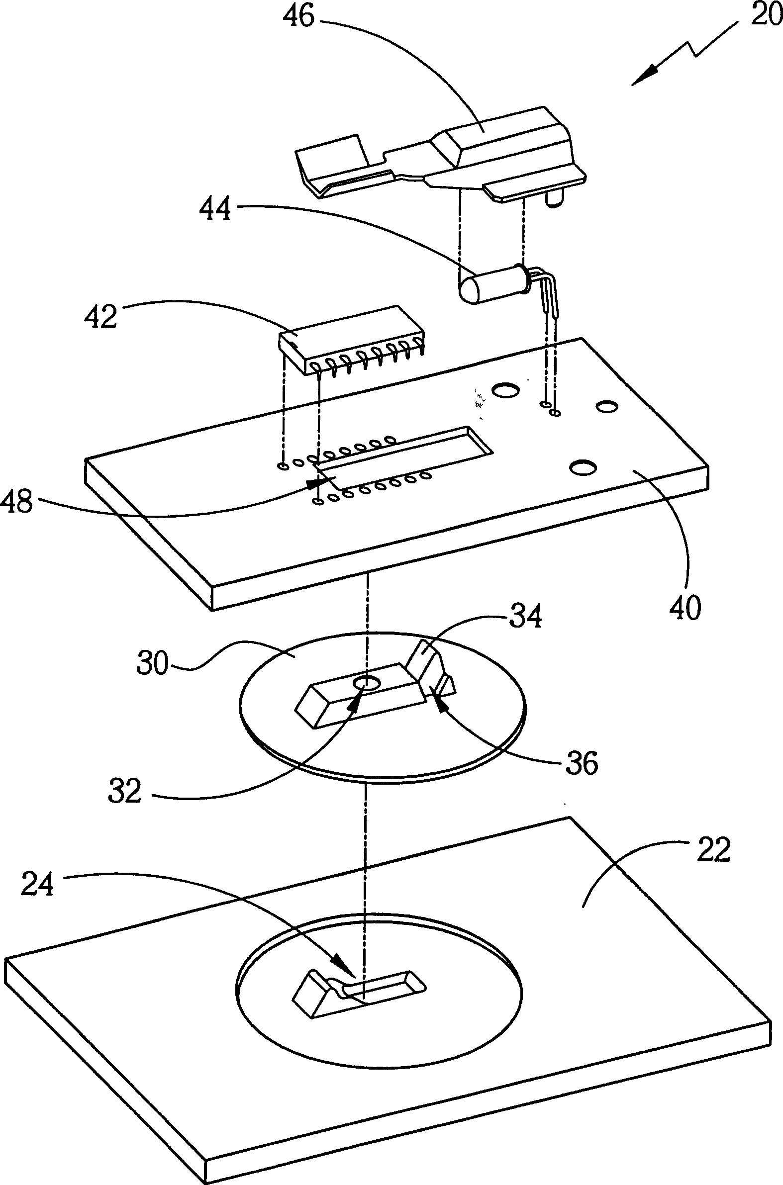
[0019] Please refer to Figure 5 and Figure 6 , FIG. 5 is a schematic diagram of the optical sliding mouse 50 of the present invention when in use, Figure 6 It is a bottom view of the optical sliding mouse 50 in FIG. 5 . The optical sliding mouse 50 is designed to be used by an operator in a sliding manner on an external plane 100 . The optical sliding mouse 50 includes a housing 58 and a ball 60 . The housing 58 includes a flat bottom surface 52 with a first opening 54 thereon. The ball 60 is in contact with the plane at the first opening 54 , and by rolling the ball 60 , the optical sliding mouse 50 can detect the displacement and direction of the optical sliding mouse 50 sliding over the plane. The displacement and direction data generated by sliding the mouse 50 are transmitted to a computer (not shown) through a cable 56 . The cable 56 can adopt many kinds of standard specifications, such as communication connection interface (COM), PS / 2 connection interface, univers...


PUM


Abstract

An optical slide mouse with rolling ball is composed of a shell with a planar bottom having the first opening, a ball in said shell, and a light source in the shell for generating light beam to irradiate said ball, and a control circuit in the shell and having an optical recognizing unit for recognizing the change in reflected light of ball.

Description

technical field [0001] The invention relates to an optical sliding mouse, in particular to an optical sliding mouse with rolling balls. Background technique [0002] Please refer to FIG. 1 , which is a schematic diagram of a known mechanical sliding mouse 10 . As is well known, the traditional mechanical sliding mouse 10 works by sensing the rolling of a ball installed in the housing of the sliding mouse, and a part of the ball is exposed outside the housing and in contact with the outside world (such as a desktop). When the sliding mouse 10 moves on the plane, its ball will roll and thus drive the two rotating shafts of the sliding mouse 10 to rotate. The sliding mouse 10 further includes two sensors for sensing the rotation degrees of the two rotating shafts and converting the rotating amounts of the two rotating shafts into corresponding index signals. The design of the sliding mouse 10 has been widely used for many years, and is still widely used today, so no detailed ...

Claims


Application Information

Patent Timeline
IPC IPC(8): G06F3/0354
Inventor 郑宇志
Owner PRIMAX ELECTRONICS LTD
Why Eureka
Try Eureka