Lighting device for high-pressure discharge lamp

A technology for high-pressure discharge lamps and discharge lamps, which is applied to discharge lamps, lighting devices, circuits, etc., and can solve problems such as reduction of light beams and blackening of discharge containers

Inactive Publication Date: 2004-02-18
USHIO DENKI KK
View PDF1 Cites 11 Cited by
  • Summary
  • Abstract
  • Description
  • Claims
  • Application Information

AI Technical Summary

Problems solved by technology

[0012] However, on the contrary, it will not quickly turn into the arc discharge state, and will produce a glow discharge of more than ten milliseconds
This long-term glow discharge sputters onto the electrode material, causing blackening of the inner surface of the discharge vessel, resulting in a reduction in the beam of the lamp

Method used


Image

  • Lighting device for high-pressure discharge lamp
  • Lighting device for high-pressure discharge lamp
  • Lighting device for high-pressure discharge lamp

Examples


Embodiment Construction

[0032] Hereinafter, the present invention will be described using examples.

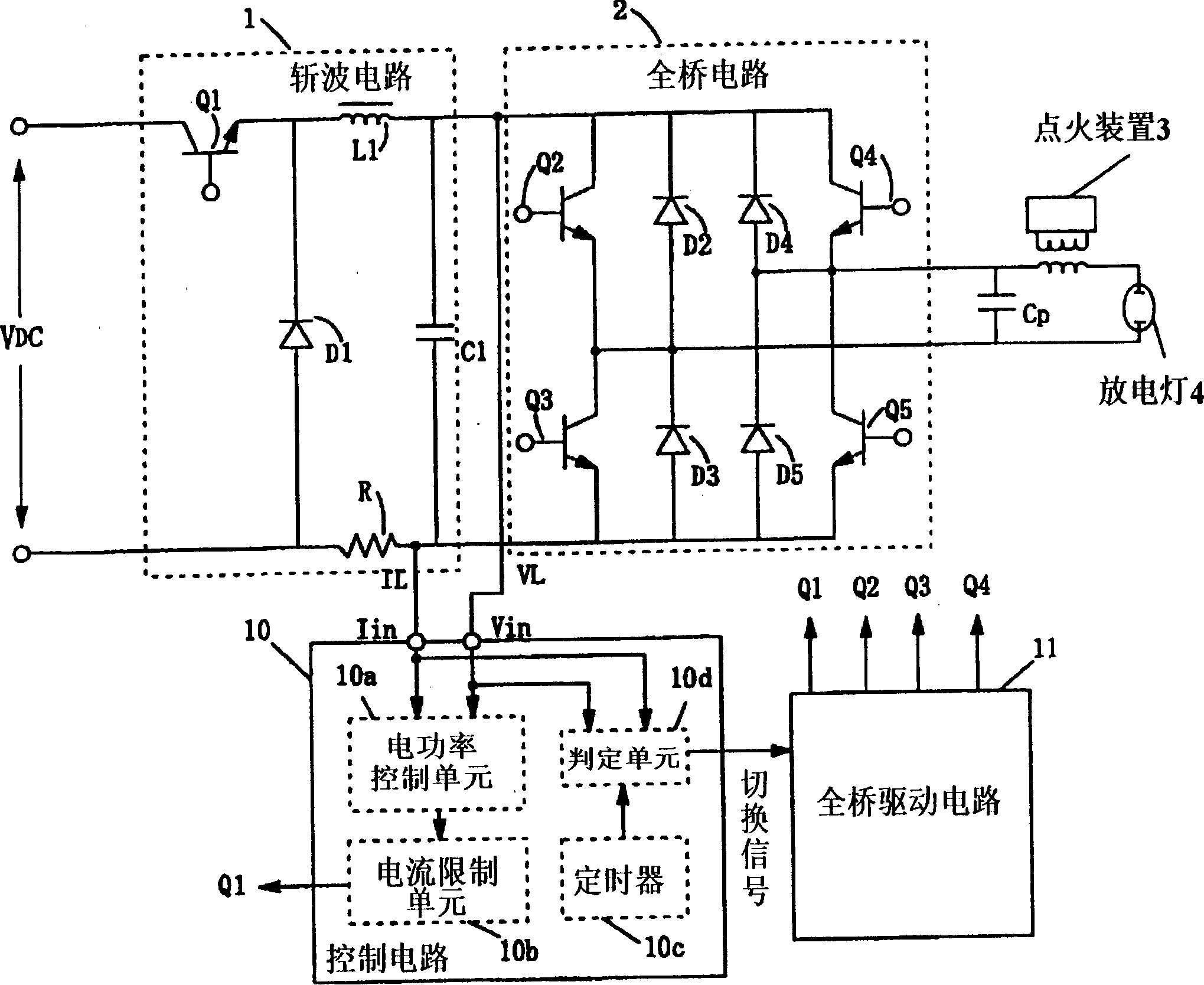
[0033] figure 1 It is a configuration diagram showing a high-pressure discharge lamp lighting device according to an embodiment of the present invention. This figure shows the configuration of a lighting circuit using a full-bridge circuit, but a half-bridge circuit or a push-pull circuit can also be used.

[0034] As shown in this figure, the circuit of the present embodiment consists of a step-down chopper circuit 1 supplying DC voltage; a full bridge circuit 2 that connects the output terminal of the step-down chopper circuit 1 to convert the DC voltage into a rectangular wave voltage; and The ignition device 3 that generates high-voltage pulses when the lamp is started is constituted, and the AC rectangular wave voltage or DC voltage output by the full bridge circuit 2 is applied to the discharge lamp 4 . A bypass capacitor Cp is connected in parallel to the output end of the full bridge circui...


PUM


Abstract

A device which improves the starting of a high pressure discharge lamp containing a large amount of mercury, in which the amount of mercury adhering to the lamp electrodes is not the same, by shortening the formation time of the glow discharge in order to reduce the sputtering of the electrodes to a minimum. When the discharge lamp starts, an AC voltage with rectangular waves produced by the full bridge circuit is applied to the discharge lamp. Next, a high voltage pulse is superimposed and applied by an igniter device; the pulse is synchronized to the polarity of the above described AC voltage with rectangular waves. As a result, an alternating current discharge is started in the discharge lamp. Then, the ON / OFF state of the switching devices in the full bridge circuit is fixed and a direct current voltage is applied to the lamp. After a pre-selected time has expired after the transition into direct current operation, the full bridge circuit is operated such that rectangular alternating current waves form. The AC voltage with rectangular waves is then applied to the discharge lamp and a transition into steady-state operation is carried out.

Description

technical field [0001] The present invention relates to a lighting device for a high-pressure discharge lamp, in particular to a lighting device for a high-pressure discharge lamp suitable for a light source of a projection projector. Background technique [0002] As a lighting device for a discharge lamp, there is a well-known circuit that uses a full-bridge switching circuit to superimpose a high frequency of about 20 kHz on a low frequency of 50 / 60 Hz to realize lighting by using an AC high frequency. (For example, refer to Japanese Patent Publication No. 6-65175). [0003] The start-up procedure of the above-mentioned discharge lamp is to start discharging from the high-voltage pulse of the ignition circuit in the no-load state, and then use the current supplied from the power supply device to make the discharge space change from the glow discharge state to the arc discharge state to form a normal lighting state . [0004] However, the transition from the above-mention...

Claims


Application Information

Patent Timeline
Patent Type & Authority Applications(China)
IPC IPC(8): H05B41/24H05B41/18H05B41/288H05B41/38
CPCY10S315/07Y10S315/05H05B41/288H05B41/38
Inventor 有本智良铃木义一
Owner USHIO DENKI KK
Why Eureka
Try Eureka