Supercharge Your Innovation With Domain-Expert AI Agents!

Motor rotating speed control method for optical drive and its control device

A speed control, optical drive technology, applied in the recording of information on magnetic disks, instruments, magnetic recording, etc., can solve the problems of increasing complexity and manufacturing costs

Inactive Publication Date: 2004-02-25
MEDIATEK INC
View PDF0 Cites 3 Cited by
  • Summary
  • Abstract
  • Description
  • Claims
  • Application Information

AI Technical Summary

Problems solved by technology

[0006] The disadvantage of the traditional speed control system is that it is necessary to precisely control the speed of the disc according to the working conditions of the optical drive, along with the position of the digital data stored on the disc.
The closed-loop design of the traditional speed control system also increases the design complexity and manufacturing cost

Method used


Image

  • Motor rotating speed control method for optical drive and its control device
  • Motor rotating speed control method for optical drive and its control device
  • Motor rotating speed control method for optical drive and its control device

Examples


Embodiment Construction

[0021] The feature of the present invention is that no matter how much the rotating speed of the optical disc is at that time, the braking time required to stop the optical disc from rotating is a fixed value. The principle is explained as follows:

[0022] Please refer to formula (1):

[0023] (1) T=J×α+f×ω

[0024] To make the disc rotate, the relationship between the torque T required by the spindle motor and the moment of inertia J of the disc, angular acceleration α, friction coefficient f and rotational speed ω is shown in formula (1). Wherein, the angular acceleration α and the rotational speed ω are functions of time.

[0025] Make formula (1) Laplace transform (Laplace transform) to get formula (2): ( 2 ) - - - T s = J ( s · Ω ( s ...


PUM


Abstract

The present invention relates to a motor rotating speed control method for optical driver. When the rotation angular speed of the optical disk is fixed and its direction is identical to turning moment, a brake moment whose moment is identical to turning moment and direction is opposite to that of turning moment can be applied to make optical disk stop rotate, otherwise, firstly a fixed moment identical to rotation angular speed can be applied to make optical disk have fixed angular speed, then a brake moment whose moment is identical to fixed moment and direction is opposite to that of fixed moment is more applied so as to make the optical disk stop rotate, so that regardless of rotating speed of optical disk it can make optical disk stop rotate in fixed time.

Description

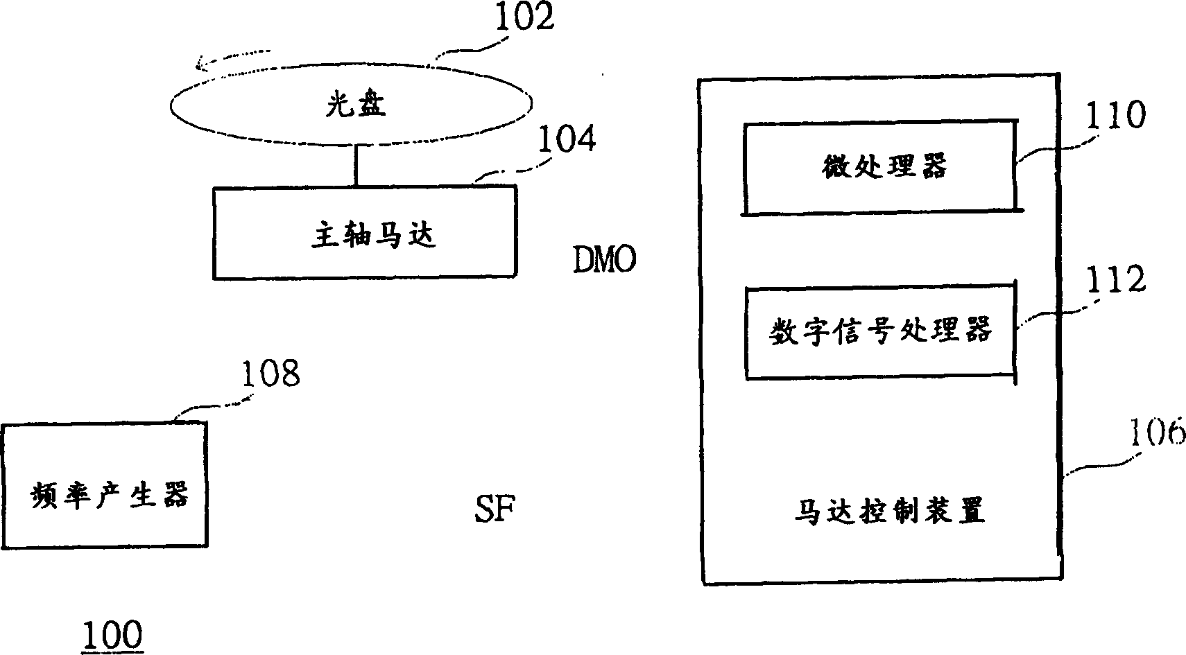
technical field [0001] The invention relates to a motor speed control method and a motor speed control device, in particular to a motor speed control method and a motor speed control device for an optical drive. Background technique [0002] As the demand for high-capacity storage media increases, the use of optical discs is increasingly playing an important role. When reading an optical disc, how to quickly and stably read the data on the disc so as to reduce the data access time (data access time) is a research topic that various manufacturers are devoting themselves to. [0003] Please refer to figure 1 , shows a circuit block diagram of a rotational speed control system 100 of a conventional optical drive. In a conventional optical drive, a disc (disc) 102 is placed on top of a spindle motor (Spindle Motor) 104 . The spindle motor 104 applies a rotational torque to the optical disc 102 according to the rotational speed control signal DMO output by the motor control de...

Claims


Application Information

Patent Timeline
Patent Type & Authority Applications(China)
IPC IPC(8): G11B19/20G11B19/28
Inventor 沈永錤
Owner MEDIATEK INC
Features
  • R&D
  • Intellectual Property
  • Life Sciences
  • Materials
  • Tech Scout
  • Unparalleled Data Quality
  • Higher Quality Content
  • 60% Fewer Hallucinations
Learn More