Needle-use threading device having height regulatable thread push pedal

A threader and pusher technology, applied in the field of needle threader, can solve the problems of complex overall structure, difficulty in determining, adding parts, etc.

Inactive Publication Date: 2004-03-10
MEDICAGO INC
View PDF0 Cites 6 Cited by
  • Summary
  • Abstract
  • Description
  • Claims
  • Application Information

AI Technical Summary

Problems solved by technology

[0007] However, providing multiple threading mechanisms will generally increase the number of parts in the threading machine, complicate the overall structure and lead to increased production costs
In addition, it also makes the threading machine bulky and inconvenient for storage and portability
In addition, when a thin needle is in

Method used


Image

  • Needle-use threading device having height regulatable thread push pedal
  • Needle-use threading device having height regulatable thread push pedal
  • Needle-use threading device having height regulatable thread push pedal

Examples


Embodiment Construction

[0037] Preferred embodiments of the present invention will be described in detail below with reference to the accompanying drawings.

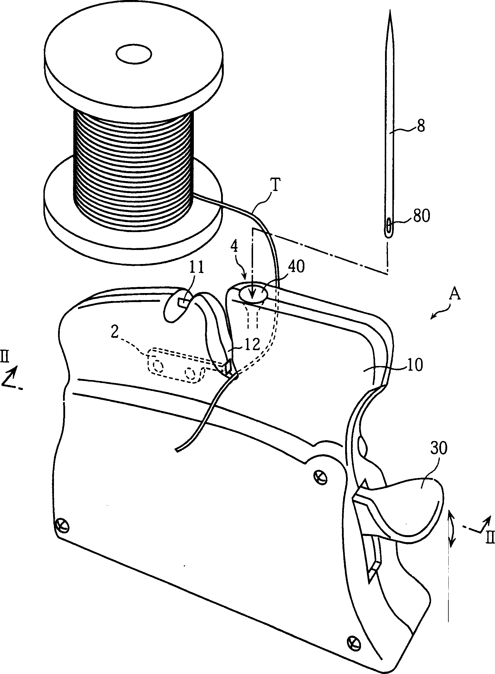
[0038] Picture 1-1 2 shows a needle threader according to an embodiment of the present invention. The appearance of the needle threader A of this embodiment is shown in figure 1 , where for the push plate operation the figure 2 The operating mechanism 3 shown is housed in a housing 10 of synthetic resin.

[0039] The housing 10 includes a side surface from which an operating rod 30 protrudes for controlling the operating mechanism 3 . The upper part of the housing 10 is provided with a needle holder 4 for holding the needle 8 in an upward posture; a cutter 11 for cutting the thread; and a valley-shaped depression 12 . When the needle threader A is used, a part of the thread  is blocked by the bottom of the valley-shaped depression 12.

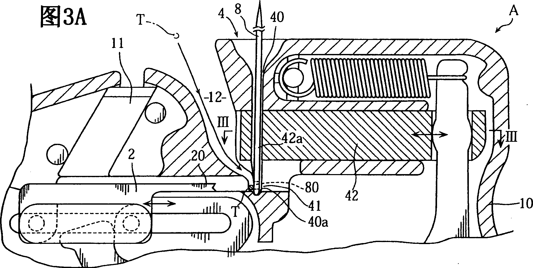
[0040] As clearly shown in FIG. 3A , the needle holder 4 includes a needle receiving hole 40 with a ...


PUM


Abstract

A needle threader is provided with a needle holder for holding a needle, and a pusher for inserting a thread into the eye of the needle. The pusher is horizontally movable in forward and backward directions relative to the needle holder. By the forward move, the pusher comes into contact with the needle accommodated in the needle holder. The pusher is movable longitudinally of the needle as held in sliding contact with the needle.

Description

field of invention [0001] The present invention relates to a needle threader for inserting a thread into a needle eye of a needle. Background technique [0002] A conventional needle threader is disclosed in, for example, Japanese Patent JP Publication No.: 2000-51561. As attached to this application Figure 15 As shown, a conventional needle threader includes two needle holders 91 disposed on a main body 90 . Each needle holder is provided with a holder body 91b, which is provided with a needle receiving hole 91a for inserting a needle 8 therein. A groove 92 is provided on the prescribed side of the frame body to allow the line to be positioned. The main body 90 is provided with an operating part 93 and a pair of push plates 94 . When the operating member 93 is pressed down in the direction indicated by the arrow Na, each push plate 94 rotates around the shaft 95 in the direction indicated by the arrow Nb, and advances toward the needle holder 91. Therefore, if Figure...

Claims


Application Information

Patent Timeline
IPC IPC(8): D05B87/02D05B87/00
CPCD05B87/00
Inventor 田中淳之
Owner MEDICAGO INC
Why Eureka
Try Eureka