
Fuel cell electric equipment electronic board manufacturing method of electric board connector for fuel cell wiring member and mounting method of fuel cell

A fuel cell and electronic equipment technology, applied in the direction of fuel cell components, fuel cells, fuel cell integration, etc., can solve the problems of equipment shape increase, complex assembly work, increase in quantity, etc., and achieve output power loss reduction, Simple fixation, limit reduction effect

Inactive Publication Date: 2004-03-24
SONY CORP
View PDF0 Cites 11 Cited by
  • Summary
  • Abstract
  • Description
  • Claims
  • Application Information

AI Technical Summary

Problems solved by technology

Then, the number of parts increases, and the shape of the device itself increases, thereby complicating the assembly work

Method used


Image

  • Fuel cell electric equipment electronic board manufacturing method of electric board connector for fuel cell wiring member and mounting method of fuel cell
  • Fuel cell electric equipment electronic board manufacturing method of electric board connector for fuel cell wiring member and mounting method of fuel cell
  • Fuel cell electric equipment electronic board manufacturing method of electric board connector for fuel cell wiring member and mounting method of fuel cell

Examples


Embodiment Construction

[0053] A fuel cell according to the present invention and an electronic device employing the fuel cell will now be described in detail with reference to the accompanying drawings.

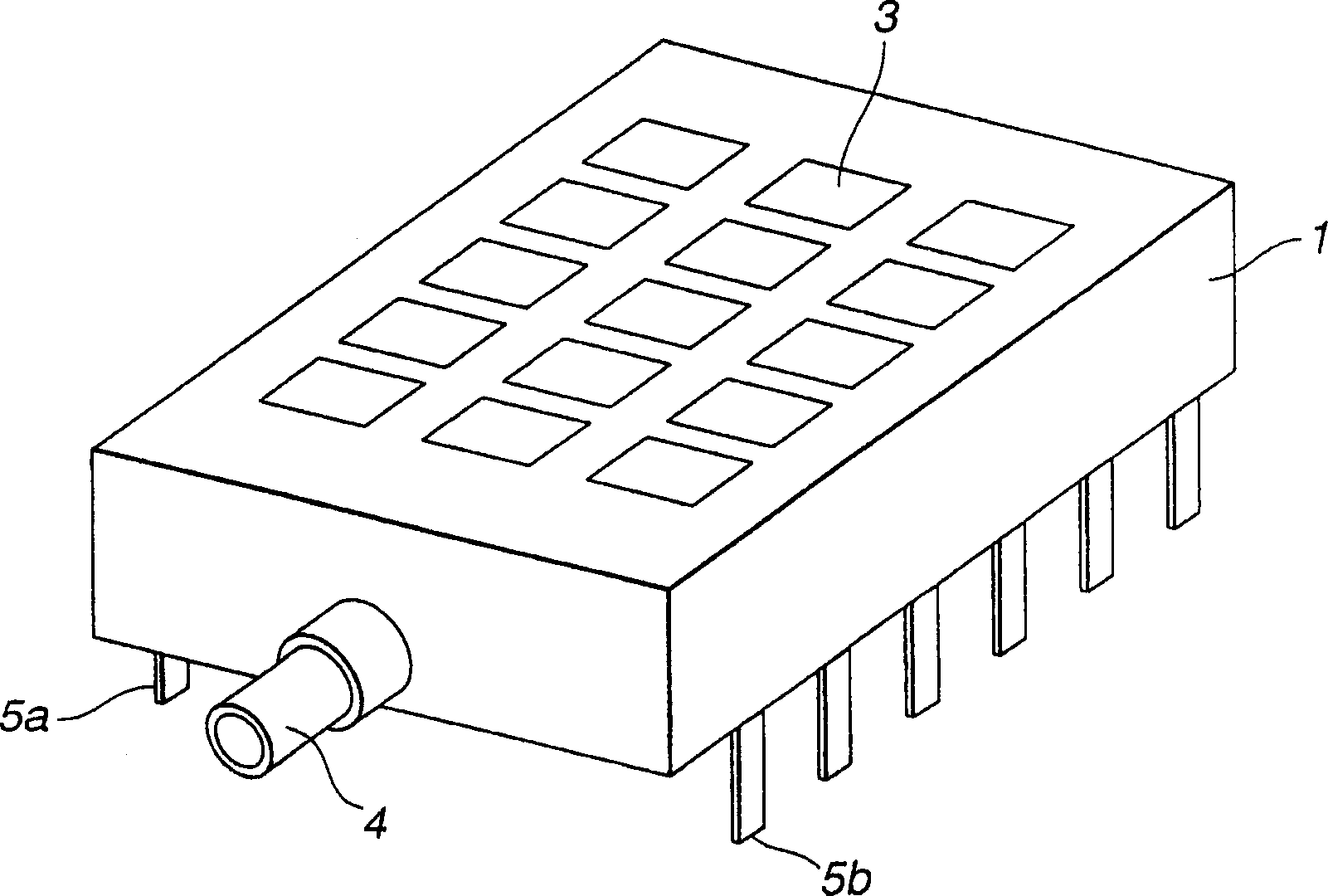
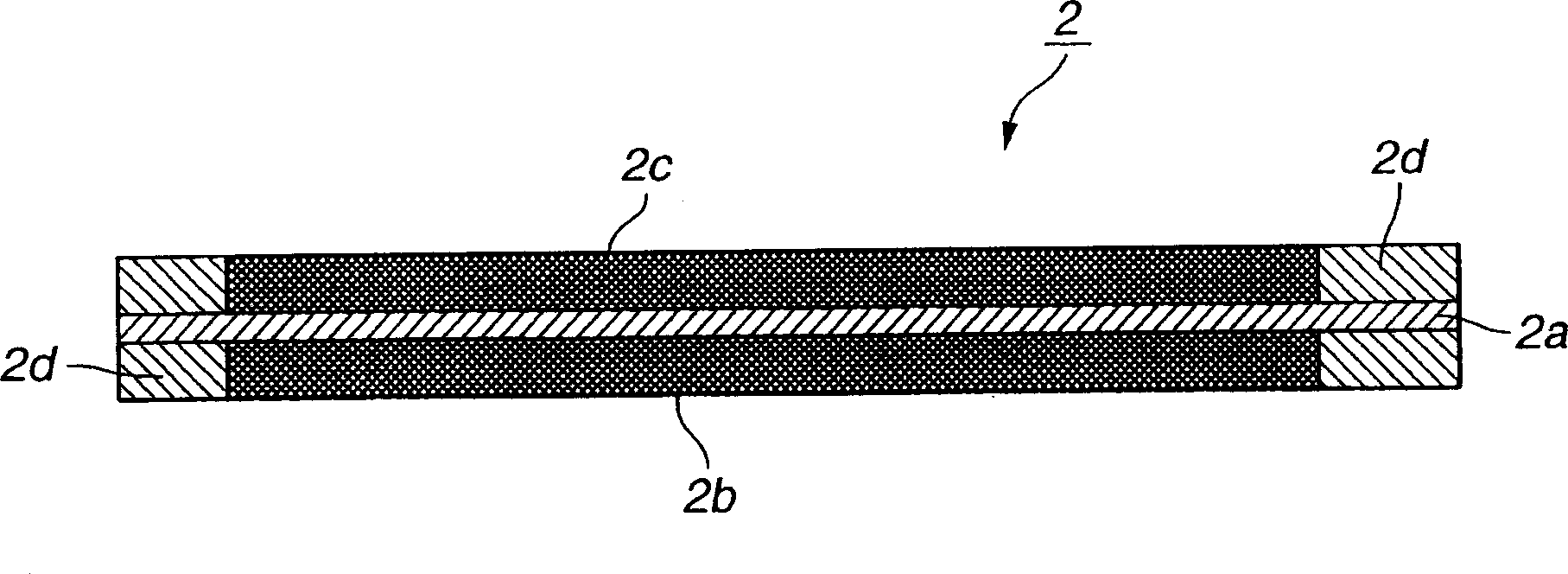
[0054] figure 1 An example of a fuel cell to which the present invention is applied is shown. figure 1 The illustrated fuel cell uses a plug-in-mount package known as a dual in-line package (DIP). One or two or more generators 2 are packed into the casing 1 . Air is supplied to the cathode side from an air inlet 3 provided on the case 1 . Fuel (hydrogen) is supplied to the anode side by a fuel connection 4 also connected to the housing 1 for power generation.

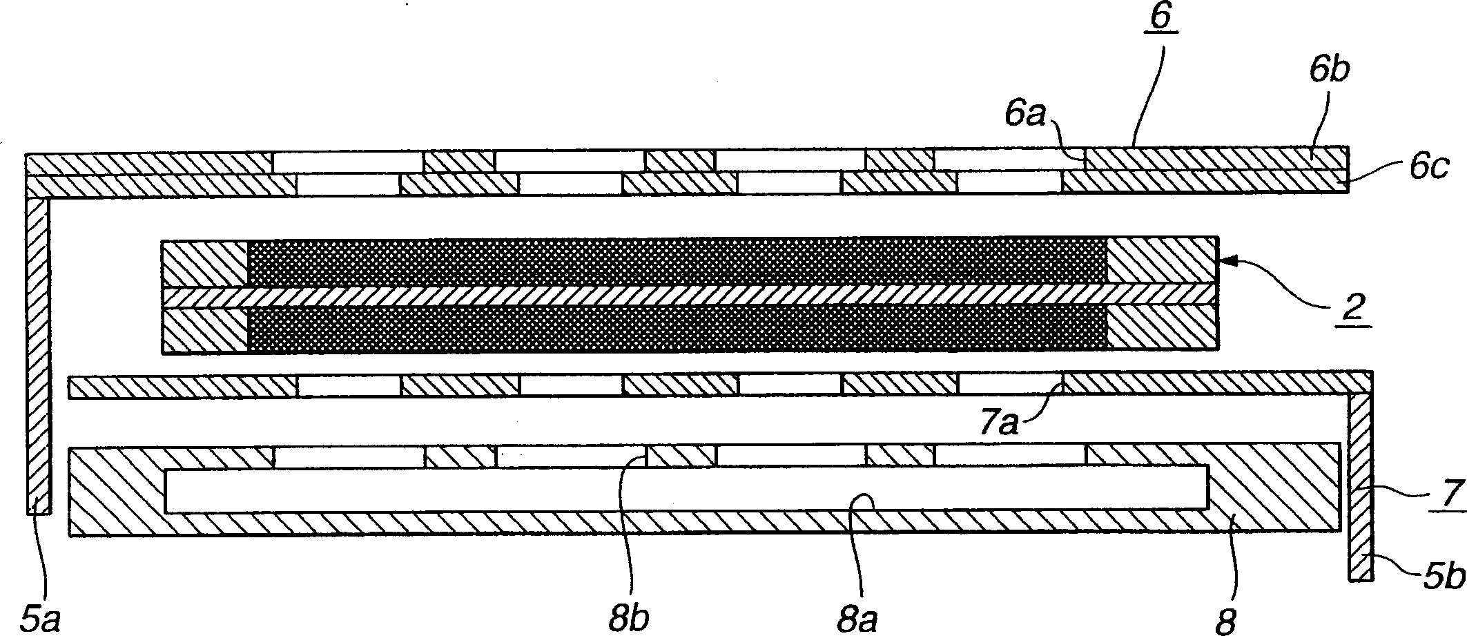
[0055] A plurality of terminal pins 5 a and 5 b connected to an anode (fuel electrode) or a cathode (air electrode) of the generator 2 are drawn out from the case 1 . The electrical connection with the electronic equipment is realized through the terminal pins 5a and 5b. That is, by, for example, inserting the terminal pins 5a and 5b in...


PUM


Abstract

The present invention relates to a fuel cell comprising a power generator (203) incorporated in a housing (201) having air intake ports (204), an electrical terminal (206) connected to a printed-wiring board (210), and connectors (205, 209b and 208b) and a fuel passage (209a) for supplying fuel. The terminals (206) are formed in such configurations as to be insertion-mounted on the printed-wiring board (210) or to be surface mounted on the printed-wiring board (210). The fuel cell is directly mounted on the printed-wiring board. Thus, a cell housing part or a fixing mechanism, a connector, etc. do not need to be provided on an electric device on which the fuel cell is mounted and the structure of the device itself is simplified and miniaturized.

Description

technical field [0001] The present invention relates to a fuel cell that generates electromotive force in a power generator by supplying hydrogen and oxygen (air) as fuel gases, and electronic equipment using the fuel cell. Background technique [0002] A fuel cell that has been introduced so far is a device that generates electromotive force in a generator by supplying hydrogen and oxygen (air) as fuel gases. The structure of such a fuel cell is generally such that an electrolyte membrane (proton-conducting membrane) is sandwiched between gas electrodes to obtain the required electromotive force. Such fuel cells have been expected to be used in electric vehicles or hybrid type vehicles, and have been gradually developed for practical use. Fuel cells are already used in vehicles, such as motor vehicles. Furthermore, by taking advantage of their advantages of being light in weight and compact in shape easily, the use of fuel cells has been studied for new uses completely di...

Claims


Application Information

Patent Timeline
Patent Type & Authority Applications(China)
IPC IPC(8): G03F7/20H01M8/02H01M8/04H05K1/02H05K3/46
CPCH05K3/4652H01M8/0258H05K1/0272H01M8/04089Y02B90/18Y02E60/50H01M8/1097H01M2250/30H05K3/4697H01M8/04201H05K3/4623H01M8/0269H01M8/0228Y02B90/10Y02P70/50H01M8/02H01M8/24
Inventor 高井雄一渡辺康博
Owner SONY CORP
Learn More