Electromagnetic braking device and apparatus for detecting abnormal of lift

An electromagnetic braking and abnormal detection technology, which is applied in the direction of braking transmissions, elevators, brakes, etc., can solve problems such as complicated steps and errors in temperature sensor measurement values

Inactive Publication Date: 2004-04-07
HITACHI BUILDING SYST CO LTD
View PDF1 Cites 23 Cited by
  • Summary
  • Abstract
  • Description
  • Claims
  • Application Information

AI Technical Summary

Problems solved by technology

[0005] However, in the above-mentioned conventional devices, the judgment of abnormality of the electromagnetic brake is performed by comparing the measured value measured by the temperature sensor with the judgment value.
However, the air temperature of the place where the elevator is installed varie...

Method used


Image

  • Electromagnetic braking device and apparatus for detecting abnormal of lift
  • Electromagnetic braking device and apparatus for detecting abnormal of lift
  • Electromagnetic braking device and apparatus for detecting abnormal of lift

Examples


no. 1 Embodiment approach

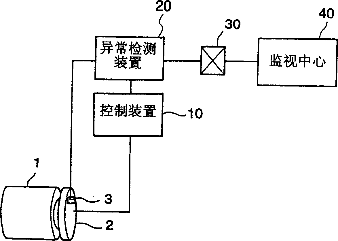
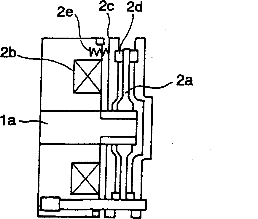
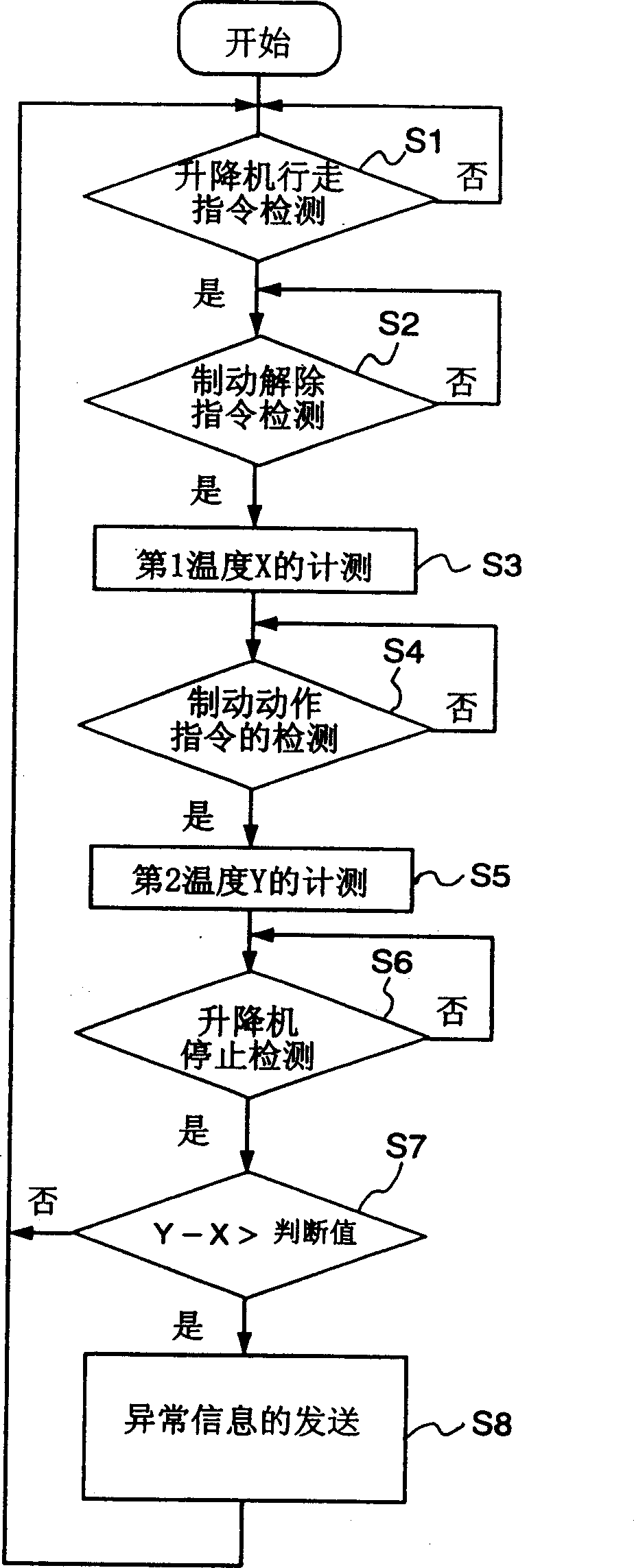
[0047] figure 1 It is a schematic configuration diagram showing the abnormality detection device of an elevator according to the first embodiment of the present invention, figure 2 It is a configuration diagram of an electromagnetic brake equipped in an elevator, image 3 yes means figure 1 The program block diagram of the action steps of the abnormality detection device.

[0048] General lifts such as figure 1 As shown, the car not shown in the figure is raised and lowered with the driving force given by the motor 1, and the electromagnetic brake 2 installed on the motor 1 gives braking force to stop the car. In addition, the motor 1 and the electromagnetic brake 2 are controlled by the control device 10 .

[0049] The abnormality detection device 20 in the first embodiment is connected to the control device 10, and is equipped with a temperature sensor 3 as a temperature detection device for measuring the temperature of the electromagnetic brake 2, and communicates with...

no. 2 Embodiment approach

[0060] 5 is a schematic diagram showing the configuration of an elevator abnormality detection device according to a second embodiment of the present invention. Figure 6 is a program block diagram showing the operation procedure of the abnormality detection device in FIG. 5 .

[0061] As shown in FIG. 5, the abnormality detection device 20 in the second embodiment is connected to the control device 10, and at the same time, it is equipped with a temperature sensor 3 as a first temperature detection device for measuring the temperature of the electromagnetic brake 2, and is installed on the elevator tower. The air temperature sensor 4 used as the second temperature detection device for detecting the ambient temperature in the tower is connected to the monitoring center 40 through the common circuit 30 .

[0062] As in the second embodiment Figure 6 As shown, the abnormality detection device 20 measures and stores the air temperature T in the elevator tower by the air tempera...

no. 3 Embodiment approach

[0068] Figure 7 It is a schematic diagram showing the configuration of an elevator abnormality detection device according to a third embodiment. Figure 8 yes means Figure 7 A program block diagram of the action steps of the abnormality detection device, Figure 9 It is a program block diagram showing the operation procedure of setting the daily average rise temperature of the electromagnetic brake as a judgment value in the present embodiment, and FIG. 10 is a characteristic diagram showing the temperature rise of the electromagnetic brake.

[0069] Such as Figure 7 As shown, the abnormality detection device 50 in the third embodiment is connected to the control device 10 , and is equipped with a temperature sensor 3 as a temperature detection device for detecting the temperature of the electromagnetic brake 2 , and is connected to the monitoring center 40 through the common circuit 30 . Above-mentioned temperature sensor 3 can be installed on any component of electroma...


PUM


Abstract

To accurately detect a trouble of a magnetic brake (2) by eliminating any effect of a temperature of a location at which an elevator is installed, a temperature sensor (3) is arranged to measure a temperature of the magnetic brake (2). When an armature (2c) has been attracted responsive to a brake release command, the temperature of the magnetic brake is measured as a first temperature, and before the armature returns responsive to a brake actuation command, the temperature of the magnetic brake is measured as a second temperature. The first and second temperatures are compared with each other. When a result of the comparison between the first and second temperatures is determined to be greater than a predetermined value, the magnetic brake (2) is determined to have been locked and hence, to have developed a trouble.

Description

technical field [0001] The present invention relates to an electromagnetic brake device capable of detecting an abnormality of an electromagnetic brake controlled by a current flowing into a coil, and an elevator abnormality detection device using the electromagnetic brake device for an elevator driving motor. Background technique [0002] Electromagnetic brakes are generally used in the braking of elevators. The action of this electromagnetic brake is: by making the current flow into the coil to attract the armature, the lining is separated from the disc, so that the car can walk, and by cutting off the above-mentioned current to make the above-mentioned armature Reset, just can make above-mentioned lining contact above-mentioned disk and produce braking force. [0003] On the other hand, it is considered that the electromagnetic brake constituted in this way sometimes gets stuck due to various reasons, causing trouble to the attracting action of the above-mentioned armatur...

Claims


Application Information

Patent Timeline
IPC IPC(8): B66B5/16B60T13/66B66B5/00F16D66/00
CPCB60T13/66F16D2066/001B66B5/0006F16D2066/006F16D66/00B66B5/0025B66B5/0037B66B5/16
Inventor 渡部恭志清杉浩中井干夫石田礼松尾利昭关谷太志
Owner HITACHI BUILDING SYST CO LTD
Why Eureka
Try Eureka