Swinging hydraulic dipper shovelling machine

A swing-type excavator technology, which is applied to earth movers/shovels, mechanically driven excavators/dredgers, construction, etc., can solve problems such as the inability to ensure the size of the pedal 61, increase costs, etc., and achieve ride-and-drop Good stability, realize the effect of operating rate and cost reduction

Inactive Publication Date: 2004-04-07
KOMATSU LTD
View PDF0 Cites 6 Cited by
  • Summary
  • Abstract
  • Description
  • Claims
  • Application Information

AI Technical Summary

Problems solved by technology

[0008] (1) The cost will increase due to the installation of the pedal 61
[0009] (2) Since the pedal 61 must avoid interference with the swing bracket 70, sometimes the size of the pedal 61 cannot be ensured for small vehicles. For this reason, it is desired to ensure a smoother boarding and alighting from the pedal

Method used


Image

  • Swinging hydraulic dipper shovelling machine
  • Swinging hydraulic dipper shovelling machine
  • Swinging hydraulic dipper shovelling machine

Examples


Embodiment Construction

[0034] Refer to the following Figure 1-10 Embodiments of the present invention will be described in detail.

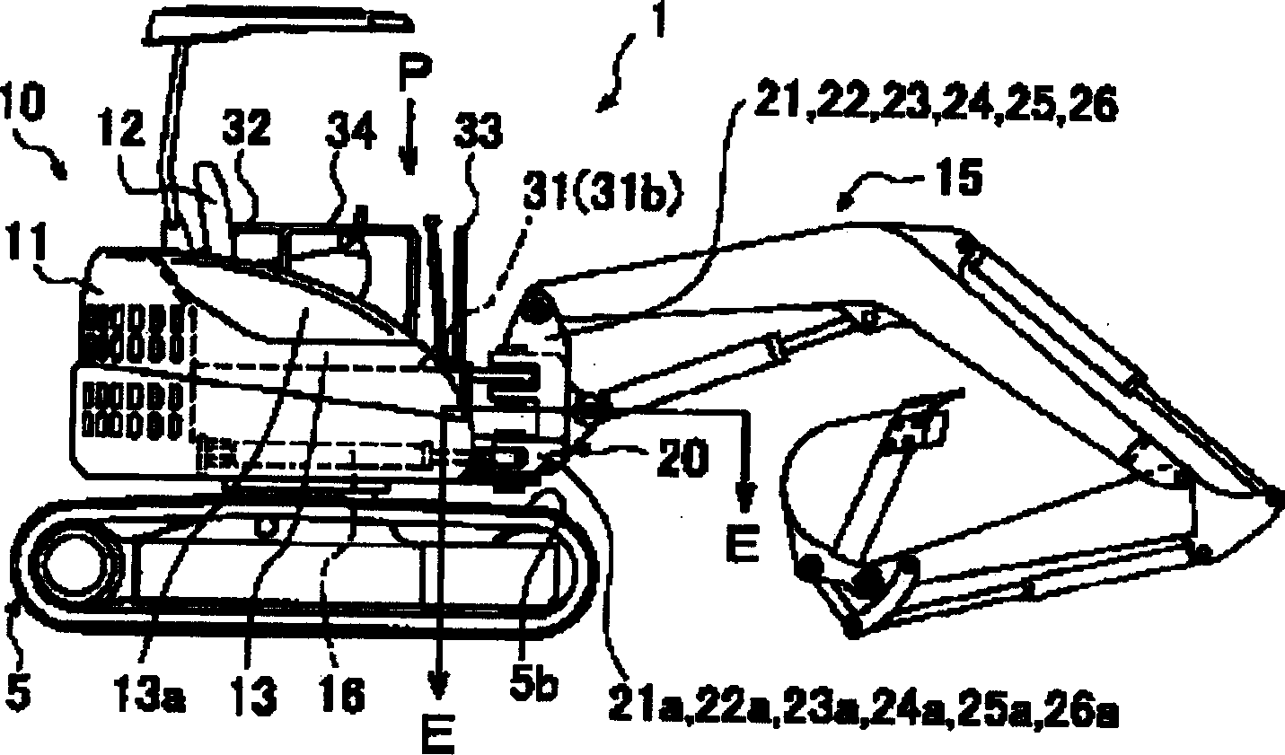
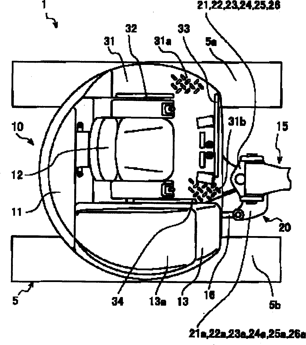
[0035] first according to Figure 1~2 Examples of the present invention will be described. figure 1 It is a side view of the swing hydraulic bucket excavator of the present invention. figure 2 It is a top view of the main part of the same hydraulic bucket excavator, which is figure 1 The P-direction view. In addition, in the following description, the same code|symbol is attached|subjected to the same component as the previous figure, and description is abbreviate|omitted.

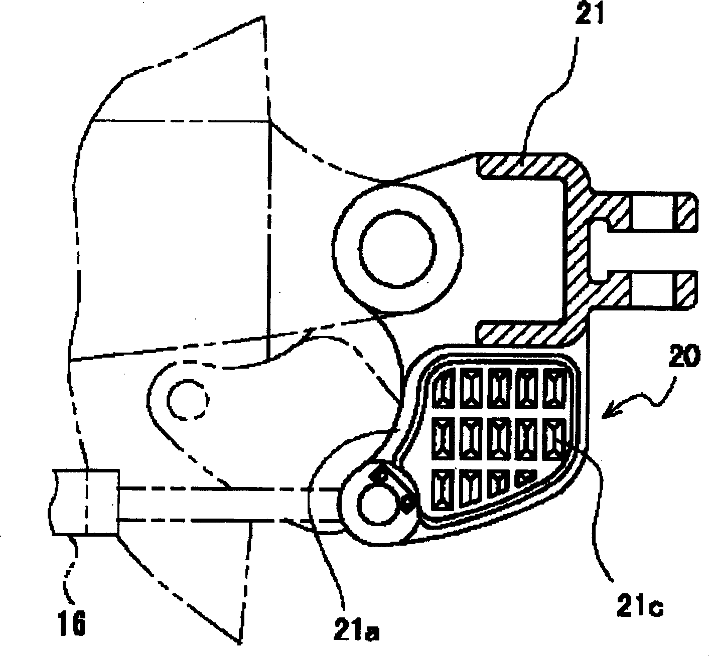
[0036] first according to Figure 1~2 , the swing type hydraulic bucket excavator 1 of the present invention will be described. In the front part of the upper rotating body 10 of the swing type hydraulic bucket excavator 1, swing brackets 21, 22, 23, 24, 25, 26, which will be described in detail in the following embodiments, are installed in the left and right direction. A work machine 1...


PUM


Abstract

In a swing type hydraulic shovel in which a working machine (15) is fitted to an upper revolving body (10) to be freely swingable right or left through a swing bracket, swinging the working machine (15) by an actuator (16) equipped between a swing bracket and the upper revolving body (10), arms (21a, 22a, 23a, 24a, 25a and 26a) for attaching the swing actuator (16) of the swing brackets (21, 22, 23, 24, 25 and 26) are made to form a stair of steps (20). Step members (25b) for a stair may be fitted to the arm (25a). It is preferable that nonslip means (21c, 22c, 23c, 24c, 25c and 26c) are installed on the arm (21a) or the step members (25b). To provide a low cost swing type hydraulic shovel capable of securing rise and fall stability at a walkthrough time regardless of the number of kinds of machines.

Description

technical field [0001] The invention relates to a swing type hydraulic bucket excavator, in particular to a swing type hydraulic bucket excavator with pedals for riding and landing. Background technique [0002] As is well known, the swing type hydraulic bucket excavator can shift the working machine relative to the center line in the front direction of the vehicle through the operation of swinging the working machine in the horizontal direction in coordination with the rotation of the upper rotating body. The construction of side ditch excavation is carried out along the side wall of the street building in the city. On the other hand, when the swing type hydraulic bucket excavator is working along the side wall of the building, since the left side of the vehicle body (usually the driver's side) approaches the building, it is sometimes desirable Usually, the machine room side) boarding and landing. In addition, during daily maintenance, approach the machine room on the righ...

Claims


Application Information

Patent Timeline
Patent Type & Authority Applications(China)
IPC IPC(8): E02F3/32E02F9/16
Inventor 池田宗义
Owner KOMATSU LTD
Why Eureka
Try Eureka