Production of high strength aluminum alloy foils

A high-strength, alloy technology, applied in the direction of metal rolling, etc., can solve the problems of inability to produce structure and microstructure effects

Inactive Publication Date: 2004-04-21
NOVELIS INC
View PDF3 Cites 4 Cited by
  • Summary
  • Abstract
  • Description
  • Claims
  • Application Information

AI Technical Summary

Problems solved by technology

For example, certain shell twists can produce multiple intermediate metal sizes and concentrations, which can negatively impact microstructural control
Therefore, the final annealing does not produce the desired structure
This makes it impossible to produce ultra-high-strength foils by strip casting

Method used


Image

  • Production of high strength aluminum alloy foils
  • Production of high strength aluminum alloy foils
  • Production of high strength aluminum alloy foils

Examples


Embodiment 1

[0028] A series of tests were carried out on a laboratory belt casting machine. The alloys used are shown in Table 1 below:

[0029] casting

No

Chemical composition (weight%)

Fe

Si

mn

note

1

1.54

0.47

-

Mn too low

2

1.55

0.46

0.09

within the scope of the invention

3

1.16

0.48

0.20

iron too low

4

1.48

0.78

0.10

within the scope of the invention

5

1.47

0.25

0.10

Si is too low

6

0.91

0.45

0.09

iron too low

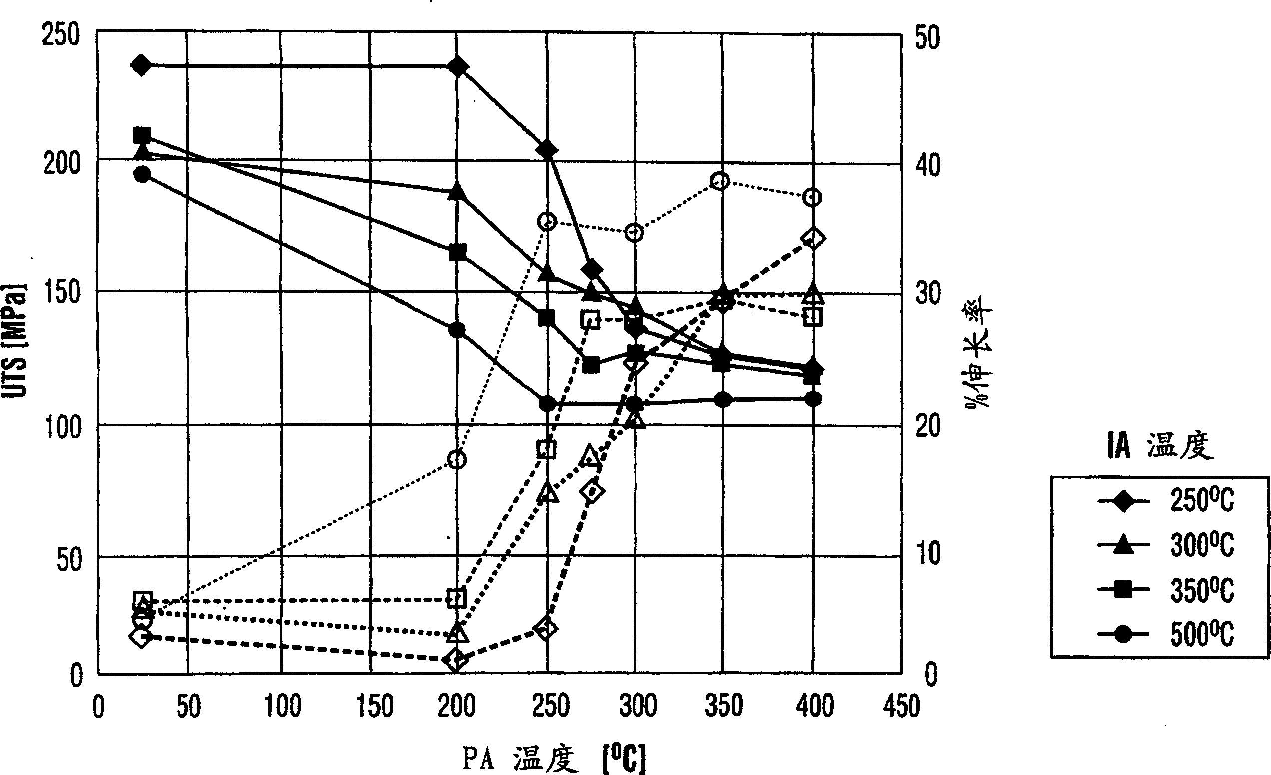
[0030] The nominal thickness of the cast strip was 7.3 mm, and all castings were free from shell distortion. Casting is carried out on a double-belt casting machine with a heat flow of 1.5-3.8MW / m 2 . This corresponds to an average cooling rate of 150-420°C / sec through the casting belt.

[0031...


PUM

PropertyMeasurementUnit
thicknessaaaaaaaaaa
thicknessaaaaaaaaaa
thicknessaaaaaaaaaa

Abstract

An aluminum alloy foil is formed from an alloy containing about 1.2 to 1.7% by weight iron, about 0.4 to 0.8% by weight silicon and about 0.07 to 0.20% by weight manganese, with the balance aluminum and incidental impurities. The alloy is continuously strip cast, e.g. on a belt caster, to form a strip having a thickness of less than about 25 mm, which is then cold rolled to interanneal gauge followed by interannealing at a temperature of about 280 to 350 DEG C. The interanneal strip is cold rolled to final gauge and further annealed to form the final foil product, having high strength and excellent quality.

Description

technical field [0001] The invention relates to the production of high-strength aluminum alloy foil products. In particular, the present invention relates to a method for producing novel aluminum alloy foils by continuous strip casting. Background of the invention [0002] Thin gauge foils are usually produced by casting aluminum alloy ingots using the so-called DC or direct chill casting method. Alloy ingots are usually heated to high temperatures, hot-rolled into rerolled gauges with a thickness of 1-10-mm, and then cold-rolled into "foil" gauges with a thickness of typically 0.2-0.4 mm. Metal strips often require intermediate annealing during cold rolling. The "foil stock" may undergo a further cold rolling process to produce a finished foil thickness of approximately 5-150 microns. [0003] In the production of this foil, if the continuous strip casting method is used at the beginning, there is no need for homogenization before hot rolling, and the amount of thermal r...

Claims


Application Information

Patent Timeline
Patent Type & Authority Applications(China)
IPC IPC(8): B21B3/00B22D11/00B22D11/06C22C21/00C22F1/04
CPCC22F1/04B22D11/00C22C21/00
Inventor I·金K·加藤拜C·加布尔耶尔
Owner NOVELIS INC
Why Eureka
Try Eureka