Automatic cleaning road, automatic cleaning system and its control method

An automatic and cleaner technology, applied in the direction of automatic control of travel movement, non-electric variable control, vehicle position/route/height control, etc., can solve problems such as inability to complete cleaning, inability to complete safe work, and reduced cleaning efficiency

Inactive Publication Date: 2004-05-05
SAMSUNG GWANGJU ELECTRONICS CO LTD
View PDF0 Cites 30 Cited by
  • Summary
  • Abstract
  • Description
  • Claims
  • Application Information

AI Technical Summary

Problems solved by technology

As a result, cleaning of some intended areas may not be completed, or cleaning of other areas may be repeated, resulting in less effective cleaning and in some cases no safe work to be done

Method used


Image

  • Automatic cleaning road, automatic cleaning system and its control method
  • Automatic cleaning road, automatic cleaning system and its control method
  • Automatic cleaning road, automatic cleaning system and its control method

Examples


Embodiment Construction

[0029] Preferred embodiments of the present invention will be described in detail below with reference to the accompanying drawings.

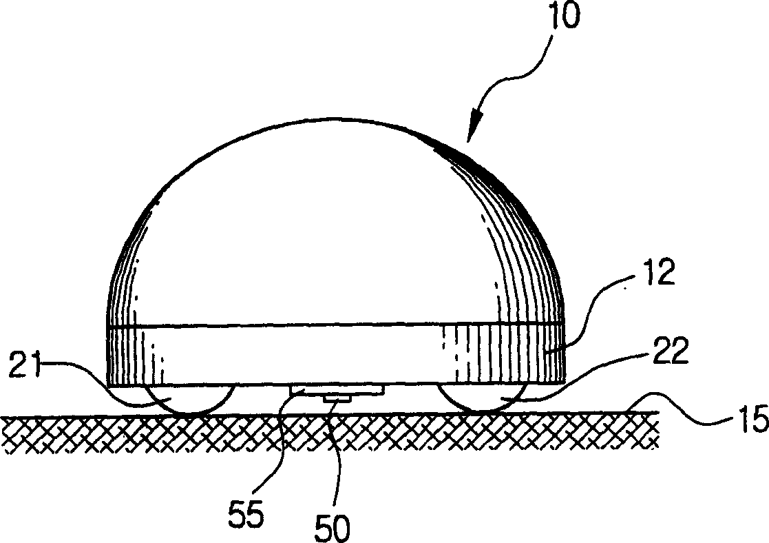
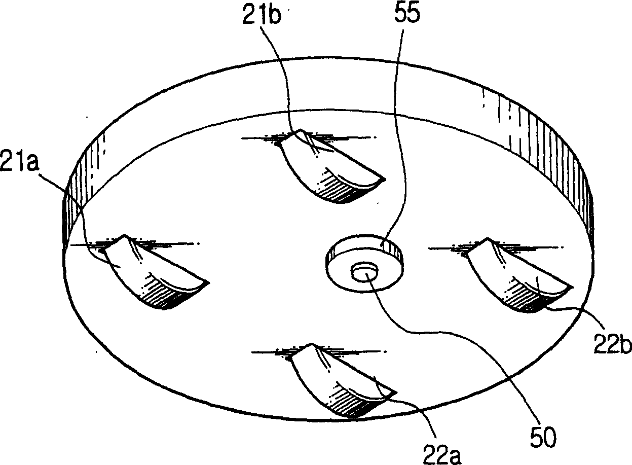
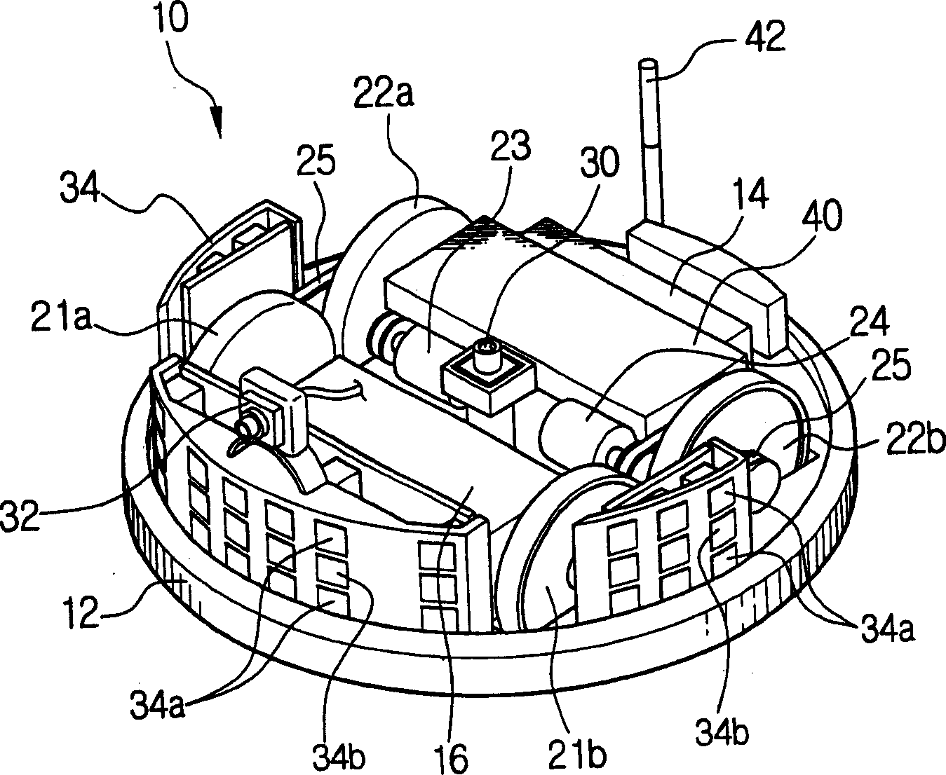
[0030] refer to figure 1 , 2A and 2B, the automatic cleaner 10 is provided with a main body 12, a suction device 16, a driving device 20, an upward patrol camera 30, a forward patrol camera 32, an obstacle detection detector 34, a downward patrol camera 50, an illumination device 55, a control means 40 , memory 41 and transmission / reception means 43 . Energy sources include stored power sources, such as batteries 14 .

[0031] The suction device 16 is installed on the main body 12 so as to collect dust such as the floor surface being cleaned when air is sucked. The inhalation device 16 can be configured using known methods. Such as suction device 16 can have suction motor (not shown in the figure), and by the driving of suction motor, for example, the suction hole or suction pipe that forms below the main body 12 with the place to be cleane...


PUM


Abstract

The robot floor cleaner (10) has a main housing with a drive for multiple wheels (21,22). It has a downward looking camera adjacent to the wheels to photograph the floor along an axis perpendicular to the travel direction. A control recognizes the driving distance and direction of the wheels using floor (15) image information to control the cleaning action. Claims include a method of cleaning floors using the robot cleaner.

Description

technical field [0001] The present invention generally relates to an automatic cleaner, an automatic cleaning system and a control method thereof, and more particularly relates to a method for identifying the driving distance and direction by using field image information captured while the automatic cleaner is moving around the field to set the driving An automatic cleaner for a path, an automatic cleaning system and a control method thereof. Background technique [0002] The traditional automatic cleaner is driven along the range of the working area surrounded by walls or obstacles and uses the ultrasonic detector installed on the main body to determine the range of the working area, and then drives it in the predetermined working area for its work, such as cleaning or safe work. path. Then, the automatic cleaner calculates the driving distance and the current position using signals detected by a detector such as an encoder capable of detecting the rotation angle and the ...

Claims


Application Information

Patent Timeline
Patent Type & Authority Applications(China)
IPC IPC(8): A47L9/28A47L9/00A47L9/30G05D1/02
CPCG05D1/0282G05D1/0246A47L9/009A47L9/2852A47L9/2894A47L9/30A47L9/2857A47L2201/04A47L9/2805G05D2201/0215A47L9/28
Inventor 宋贞坤黄允燮
Owner SAMSUNG GWANGJU ELECTRONICS CO LTD
Why Eureka
Try Eureka