Rotation reed for fishing

A technology of rotating lines and reels, which is applied in fishing reels, fishing, applications, etc., and can solve problems such as inability to maintain rolling guidance performance

Inactive Publication Date: 2004-05-19
DAIWA SEIKO CORPORATION +1
View PDF1 Cites 5 Cited by
  • Summary
  • Abstract
  • Description
  • Claims
  • Application Information

AI Technical Summary

Problems solved by technology

Therefore, stable scroll guidance

Method used


Image

  • Rotation reed for fishing
  • Rotation reed for fishing
  • Rotation reed for fishing

Examples


Embodiment Construction

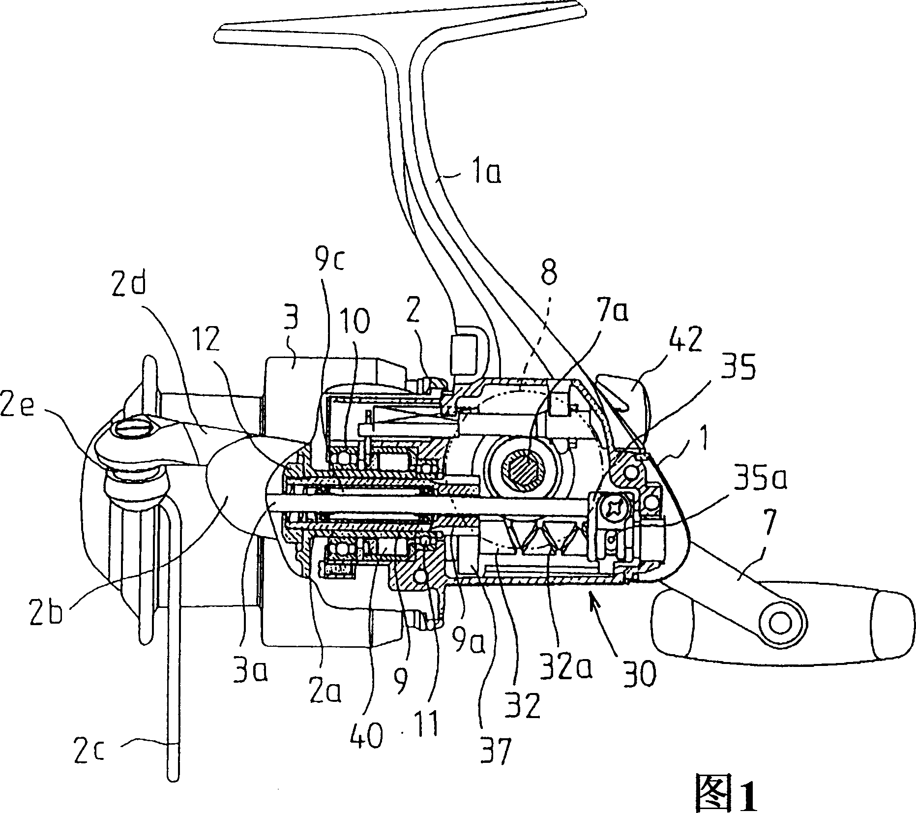
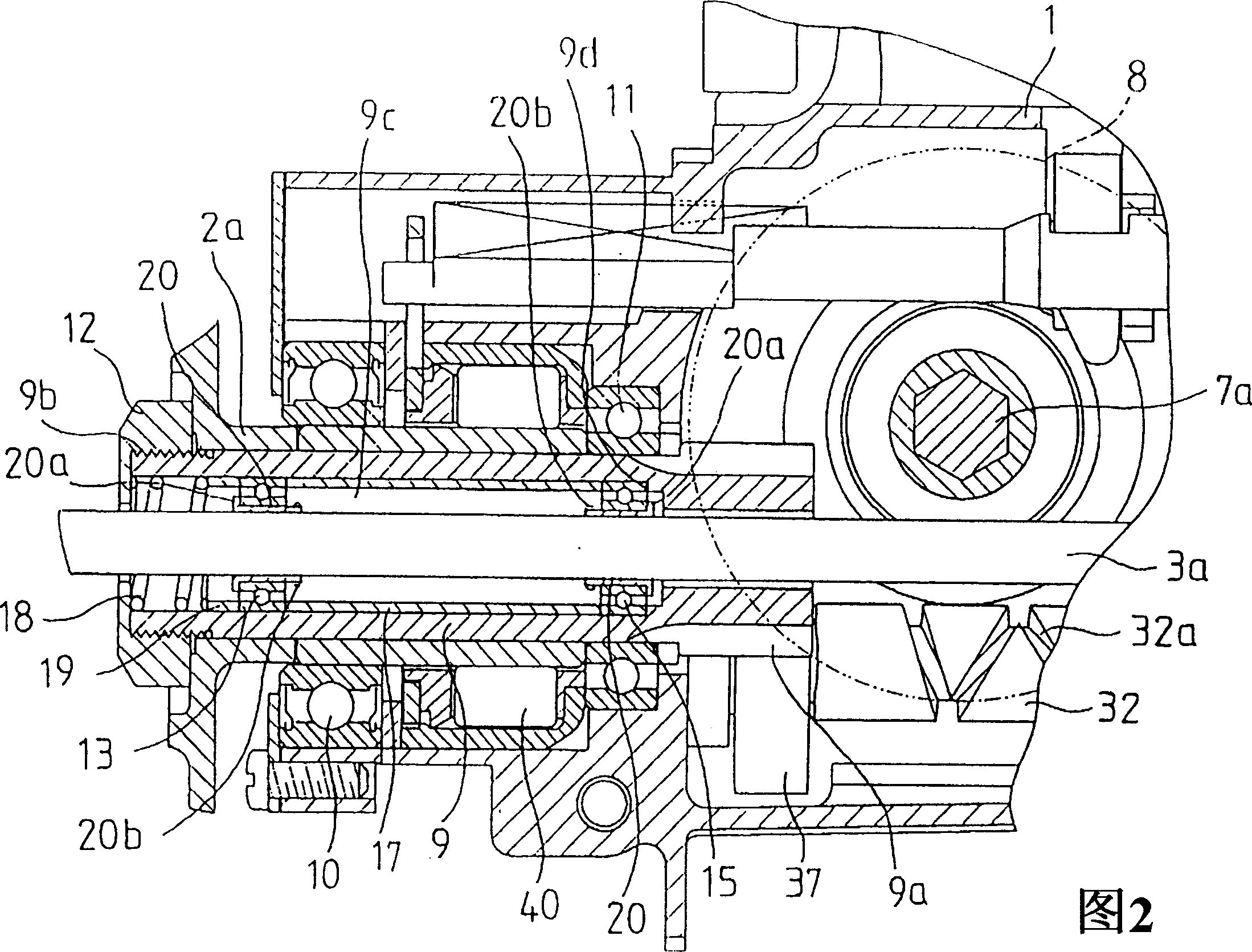
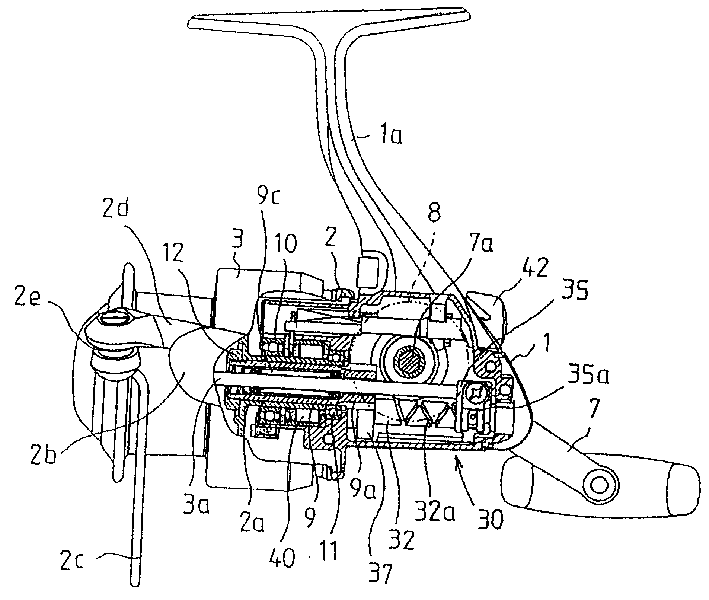
[0023] 1 and 2 are views showing an embodiment of the present invention. FIG. 1 is an overall structural view of a spinning reel for fishing, and FIG. 2 is an enlarged view of a main part of FIG. 1 .

[0024] In the reel main body 1 of the spinning reel, the line arm 1a connected to the fishing rod is integrally formed. At the front of the reel main body 1 , there are provided a rotatably supported rotor 2 and a spool 3 supported so as to be movable in the longitudinal direction in synchronization with the rotational movement of the rotor 2 .

[0025] The handle shaft 7 a is rotatably supported by the reel main body 1 . The handle 7 is connected to the protruding end portion of the handle shaft 7a. The handle shaft 7a is engaged with the winding drive mechanism. The winding drive mechanism includes: a drive gear (face gear) 8 with internal teeth connected to the handle shaft 7a; a pinion 9a meshing with this drive gear 8; and a rotating cylindrical shaft 9, the rotating cir...


PUM


Abstract

A spinning reel for fishing includes: a reel body; a pinion rotated in response to a rotation of a handle; a rotary cylinder shaft integrally rotated with a rotor including a fishing line guide portion, the rotary cylinder shaft being rotatably supported in the reel body; a spool shaft including a spool at an end portion thereof, the spool shaft being inserted into the rotary cylinder shaft so that so that the spool shaft can be reciprocated in an axial direction thereof; a recessed portion formed in the axial direction on an inner circumference side of the rotary cylinder shaft; and a pair of rolling bearings arranged so as to be separated from each other in the axial direction between the recessed portion and an outer circumferential face of the spool shaft.

Description

technical field [0001] The present invention relates to a spinning reel for fishing, with which, when a rotor having a fishing line guiding portion is turned, and at the same time, a handle connected to a winding drive mechanism of the reel main body is turned, the line is wound As the drum reciprocates in the longitudinal direction, the fishing line is wound on the spool through the fishing line guide portion. Background technique [0002] Generally, spinning reels for fishing are constructed in such a way that when the rotor is rotated under the condition that the spool shaft is loaded, the spool shaft reciprocates in the longitudinal direction, and the front end portion of the spool shaft A spool is attached and the fishing line is retrieved through the line guide portion of the rotor. The rotor is driven via a pinion (formed on a rotating cylindrical shaft) that meshes with a face gear that is connected to the handle shaft while the spool shaft is inserted into the rota...

Claims


Application Information

Patent Timeline
IPC IPC(8): A01K89/01
CPCA01K89/01
Inventor 宫坂信一郎下崎哲哉K·C·程丹尼·S·C·岳
Owner DAIWA SEIKO CORPORATION
Why Eureka
Try Eureka