Eureka AIR delivers breakthrough ideas for toughest innovation challenges, trusted by R&D personnel around the world.

Chamfering equipment used after metal plate cutting

A metal plate and chamfering technology, which is applied in the direction of metal processing equipment, metal processing, metal processing machinery parts, etc., can solve problems such as troublesome replacement of chamfering cutter heads, and low work efficiency, so as to reduce production costs and reduce installation costs. The number of clamping and moving metal plates and the effect of reducing labor intensity

Inactive Publication Date: 2021-10-01
徐州恒乾紧固件制造有限公司
View PDF13 Cites 0 Cited by
  • Summary
  • Abstract
  • Description
  • Claims
  • Application Information

AI Technical Summary

Problems solved by technology

[0003] When chamfering the upper and lower sides of the metal sheet in the prior art, the machine head is used to chamfer the upper side, then the sheet is reversed, and the lower side is chamfered. For chamfering, and each chamfering head can only be poured at a specific angle. It is very troublesome to replace the chamfering head for other angles. The special chamfering machine has a single function. When the metal sheet is uneven Irregular chamfering surface is easy to appear, and manual refueling is required. The operation process is cumbersome and the work efficiency is low.

Method used


Image

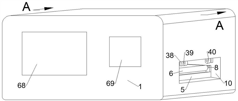
  • Chamfering equipment used after metal plate cutting
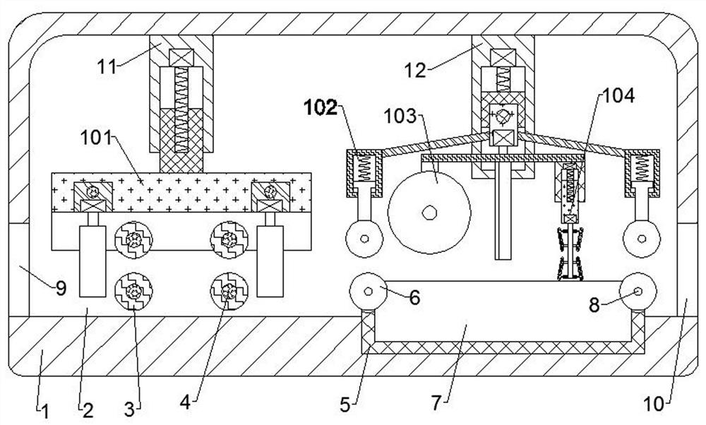
  • Chamfering equipment used after metal plate cutting
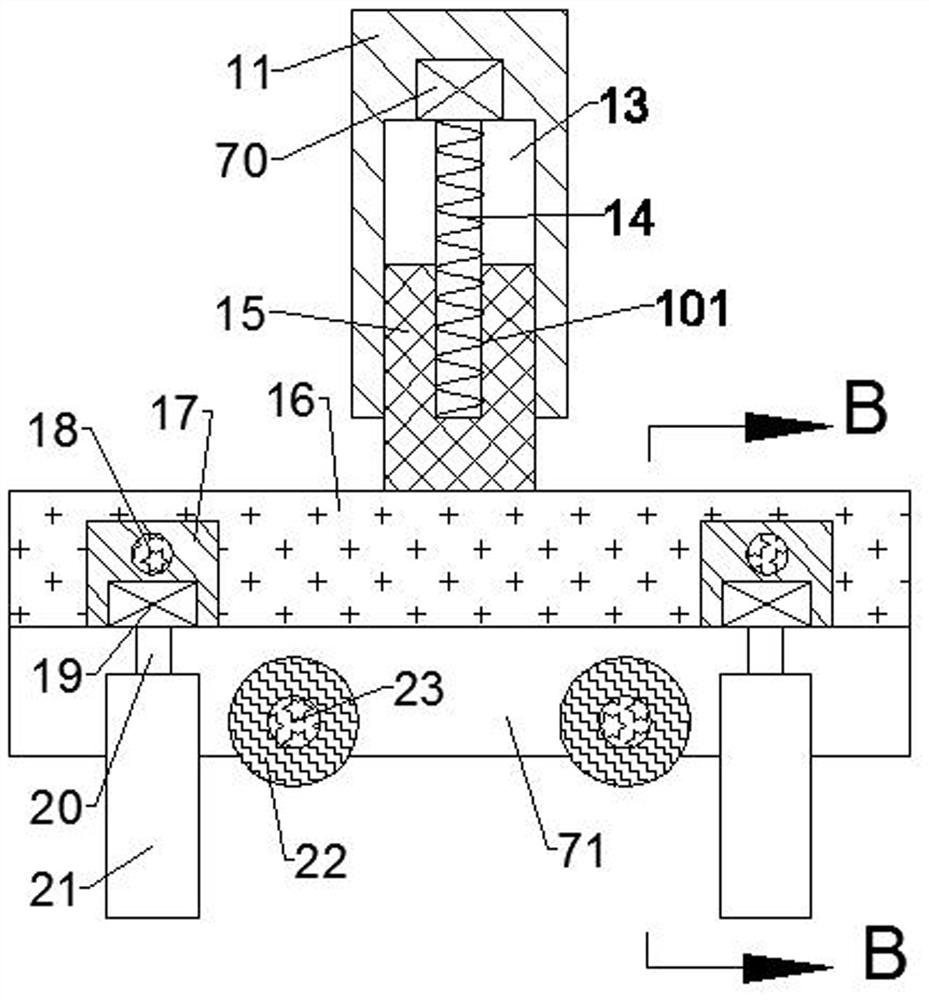
  • Chamfering equipment used after metal plate cutting

Examples


Embodiment Construction

[0023] In order to make the objects and advantages of the present invention clearer, the present invention will be described in detail below in conjunction with the examples. It should be understood that the following words are only used to describe a kind of metal plate cutting chamfering equipment or several specific implementation modes of the present invention. , does not strictly limit the protection scope of the specific claims of the present invention, as used herein, the terms up and down and left and right are not limited to their strict geometric definitions, but include reasonable and inconsistent tolerances for machining or human error, The specific features of this kind of metal plate cutting chamfering equipment are described in detail below:

[0024] Refer to attached Figure 1-9 , according to an embodiment of the present invention, a metal plate cutting chamfering equipment, including a body shell 1, the body shell 1 is provided with a working chamber 2, and t...


PUM


Abstract

The invention discloses chamfering equipment used after metal plate cutting. The chamfering equipment comprises a machine body shell, a working cavity is formed in the machine body shell, first connecting shafts are fixedly arranged in the working cavity, the left positions and the right positions of the first connecting shafts are symmetrical, leveling auxiliary wheels are rotationally arranged on the first connecting shafts, and a leveling device capable of guiding and leveling a metal plate is arranged above the leveling auxiliary wheels. According to the chamfering equipment, arranged leveling wheels cooperate with the leveling auxiliary wheels to press the metal plate, arranged clamping guide wheels are close to each other to clamp the metal plate, the leveling wheels and the clamping guide wheels can rotate at the same time, the functions of pressing, clamping and fixing the metal plate and preventing the metal plate from shaking and affecting subsequent machining, the function of pressing and leveling the surface of the metal plate and the function of feeding the metal plate rightwards are achieved, arranged pressing wheels cooperate with pressing auxiliary wheels so that the metal plate can be firmly pressed, and the function of preventing the metal plate from shaking and affecting the cutting precision during cutting is achieved.

Description

technical field [0001] The invention relates to the field of metal processing, in particular to a chamfering equipment after cutting a metal plate. Background technique [0002] Chamfering refers to the processing of cutting the edges and corners of the workpiece into a certain slope. The chamfering is to remove the burrs on the parts due to machining, and also to facilitate the assembly of the parts. Generally, the chamfering is made at the end of the parts. [0003] When chamfering the upper and lower sides of the metal sheet in the prior art, the machine head is used to chamfer the upper side, then the sheet is reversed, and the lower side is chamfered. For chamfering, and each chamfering head can only be poured at a specific angle. It is very troublesome to replace the chamfering head for other angles. The special chamfering machine has a single function. When the metal sheet is uneven It is prone to irregularities in the chamfering surface, and the manual refueling ope...

Claims


Application Information

Patent Timeline
Patent Type & Authority Applications(China)
IPC IPC(8): B23P23/02B23Q7/00B23Q7/05B23Q1/25B23Q3/06
CPCB23P23/02B23Q7/00B23Q7/05B23Q1/25B23Q3/062
Inventor 戚小乐
Owner 徐州恒乾紧固件制造有限公司
Why Eureka
Eureka Blog
Learn More