Nestable chair

A technology for chairs and chair legs, applied in the field of stackable chairs, to achieve the effect of reducing assembly parts

Inactive Publication Date: 2004-05-19
DAUPHIN ENTWICKLUNGS-U BETEILIGUNGS- GMBH (DE)
View PDF0 Cites 29 Cited by
  • Summary
  • Abstract
  • Description
  • Claims
  • Application Information

AI Technical Summary

Problems solved by technology

If this frame is used as an assembly accessory, when the chairs are stacked, the space betw

Method used


Image

  • Nestable chair
  • Nestable chair
  • Nestable chair

Examples


Embodiment Construction

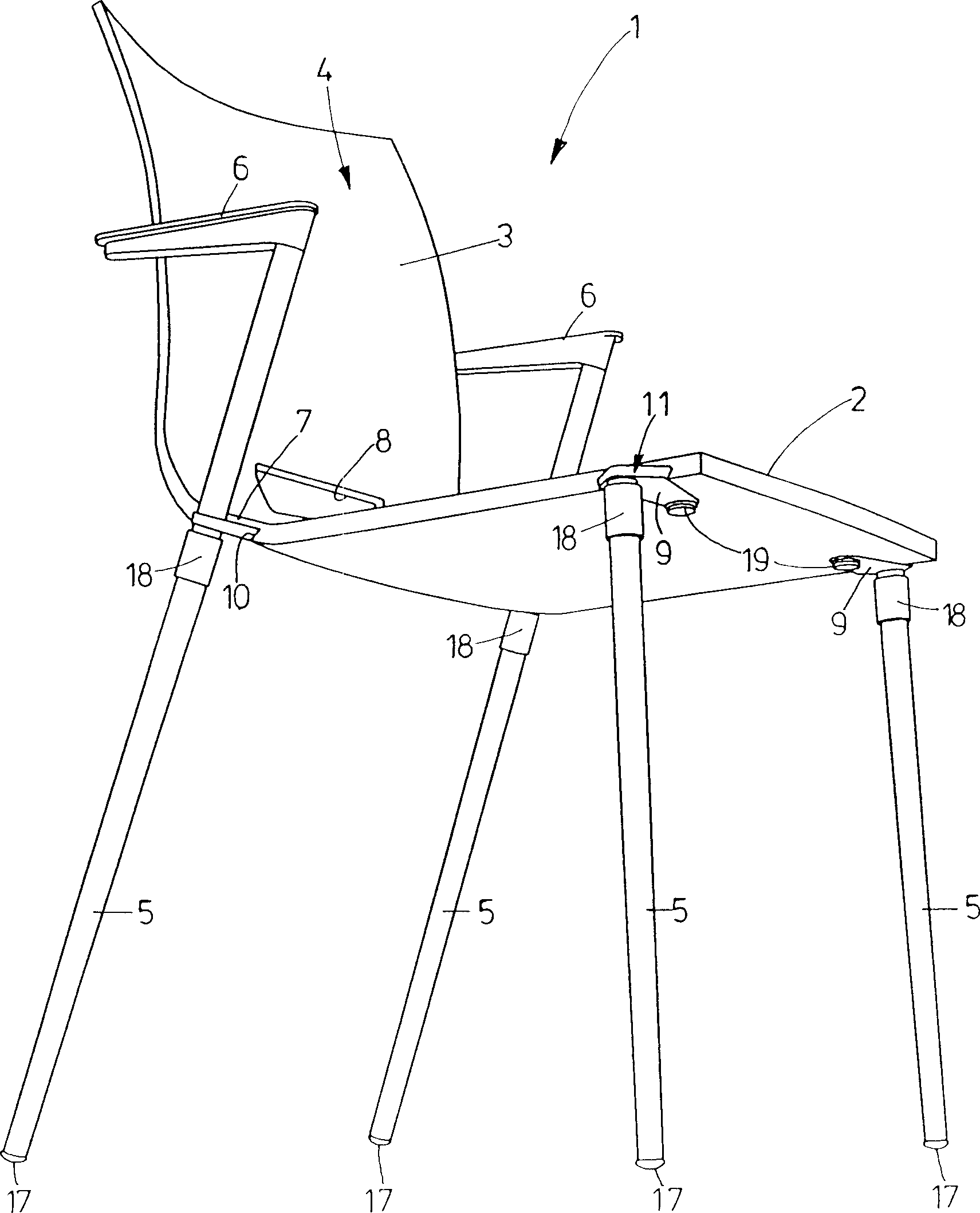
[0025] A stackable chair, generally indicated by reference numeral 1 in the figures, comprises a seat part 4 , four legs 5 and two armrests 6 , wherein the seat part comprises a seat surface 2 and a backrest 3 .

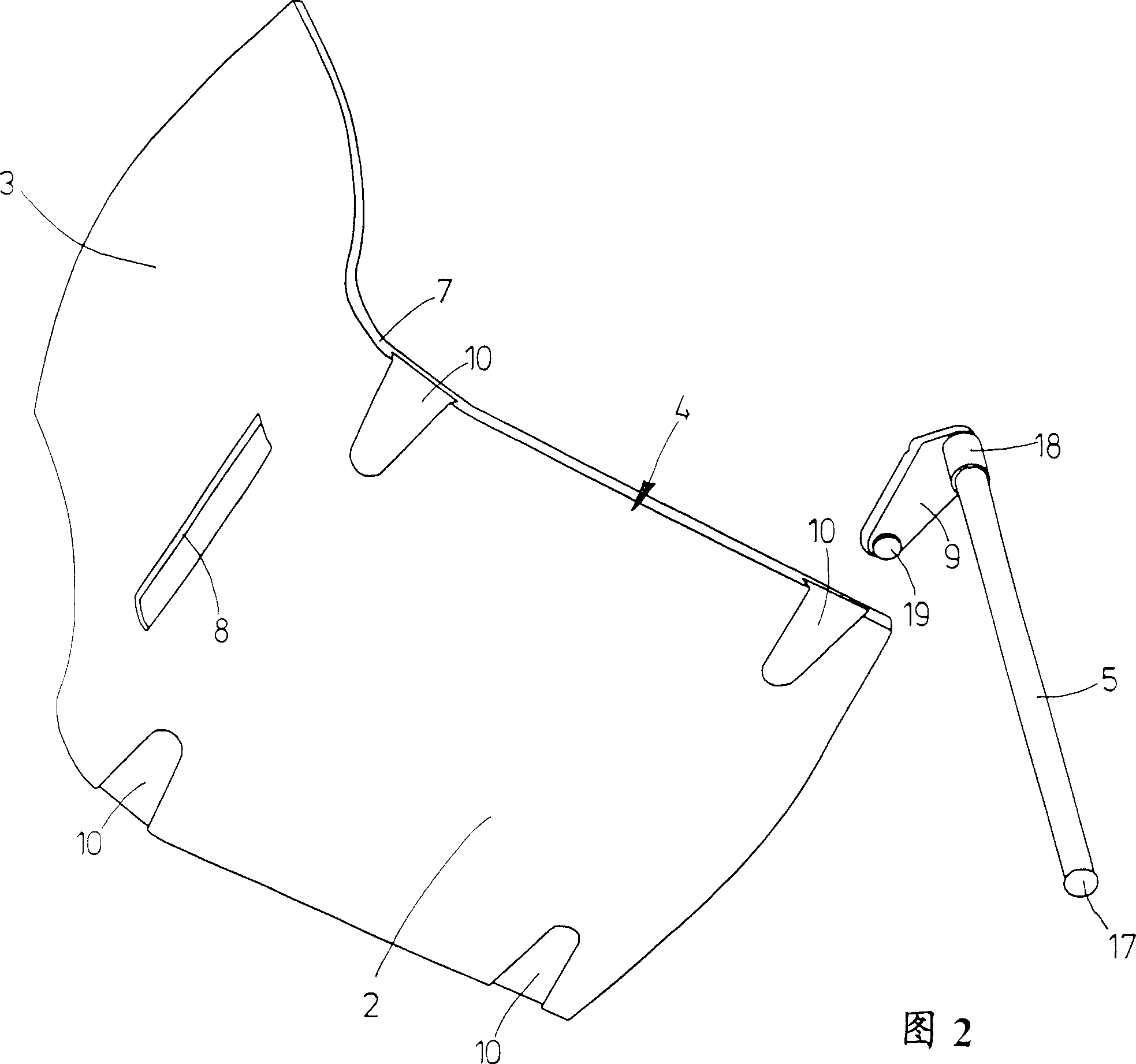
[0026] The seat part 4 has the shape of a seat shell and is made of a sheet-like plywood or plastic material. The plate-shaped material of the seat part 4 is approximately 15 mm thick. The seat surface 2 is substantially planar and transitions seamlessly into the backrest 3 via a bend 7 . The curved portion 7 does not have a uniform radius of curvature, but includes a planar portion where the seat surface and backrest join. Furthermore, the seat part 4 is provided with a rectangular opening 8 in the region of the curved portion 7 .

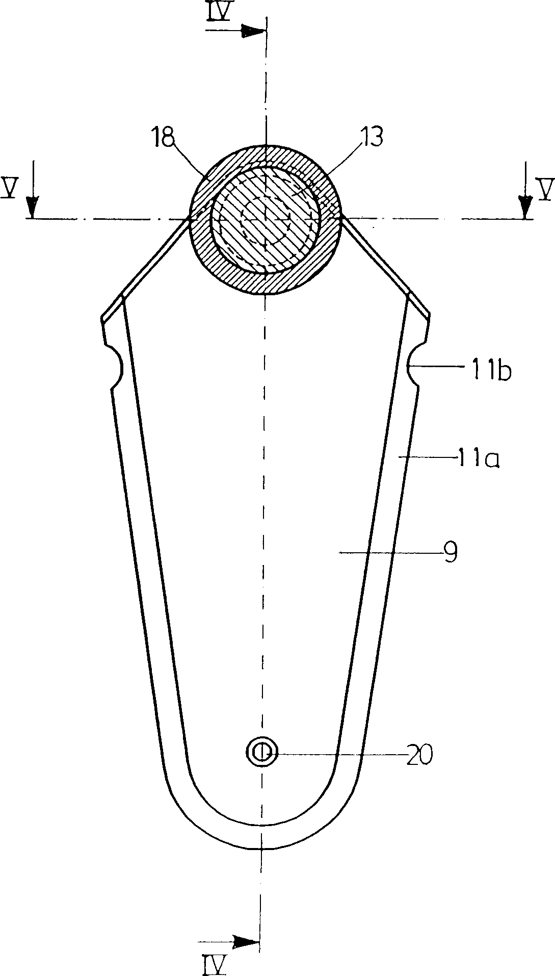
[0027] The chair leg 5 is mounted on the seat member 4 through the connecting plate 9 . To achieve this, said seat part 4 is provided for each leg 5 with a recess 10 formed complementary to the respective connecting plate 9 (shape) an...


PUM


Abstract

A stackable chair 1 includes a seating member 4 comprising a seat 2, and a plurality of chair legs 5. Each of said chair legs 5 is attached to the seating member 4 by means of its own connecting device 11. The connecting device 11 includes a connecting plate 9 which is inserted in a recess 10 of the seating member 4 such that it does not extend beyond the seating member 4 where the chair 1 is adjacent to other chairs in the stacked condition. The chair leg 5 is attached to the connecting plate 9. The result is a chair 1 which can be stacked in a compact manner.

Description

technical field [0001] The invention relates to a stackable chair, which comprises a seat and a plurality of chair legs connected to the seat. Background technique [0002] Such stackable chairs are so well known that their use is now obvious. In these known chairs, the legs are connected to the seat part by at least one frame element, which is located below the seat surface and connects the legs to each other. If such a frame member is used as an assembly, when the chairs are stacked, the space between the chairs is still large, and therefore, a large space is required even if the chairs are stacked. Contents of the invention [0003] It is thus an object of the present invention to further improve the above-mentioned chair so that it can be stacked in a more compact manner. [0004] According to the invention, said object can be achieved by such a stackable chair, which [0005] - includes a seat with a seat surface, [0006] - includes multiple chair legs, [0007]...

Claims


Application Information

Patent Timeline
IPC IPC(8): A47C3/04
Inventor M·巴伦达特
Owner DAUPHIN ENTWICKLUNGS-U BETEILIGUNGS- GMBH (DE)
Why Eureka
Try Eureka