Weft holding device in fluid spraying type weaving machine

A fluid jet and weft yarn technology, applied in looms, auxiliary equipment for weaving, textile and other directions, can solve the problems of large time difference, difficult to accept weft yarn, weft yarn detachment, etc., to prevent cloth defects and improve responsiveness.

Inactive Publication Date: 2004-05-19
KAIHARA +1
View PDF2 Cites 4 Cited by
  • Summary
  • Abstract
  • Description
  • Claims
  • Application Information

AI Technical Summary

Problems solved by technology

Therefore, in the two conventional technologies, when the swing range of the holding members is small, it is difficult to receive the weft yarn between the holding members, and when the swing range of the holding members is large, the time difference between the output of the holding command and the actual holding of the weft y

Method used


Image

  • Weft holding device in fluid spraying type weaving machine
  • Weft holding device in fluid spraying type weaving machine
  • Weft holding device in fluid spraying type weaving machine

Examples


Example Embodiment

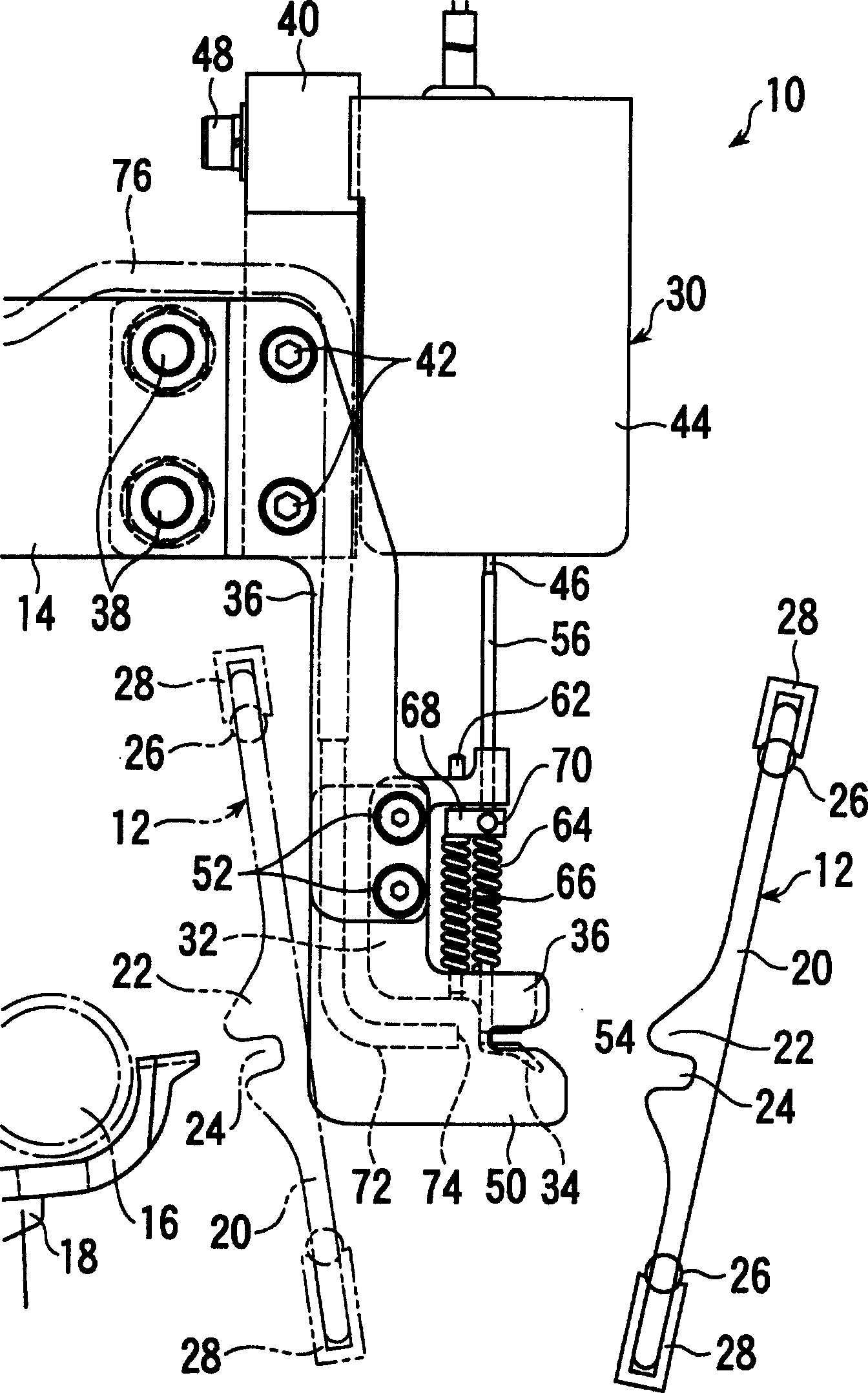
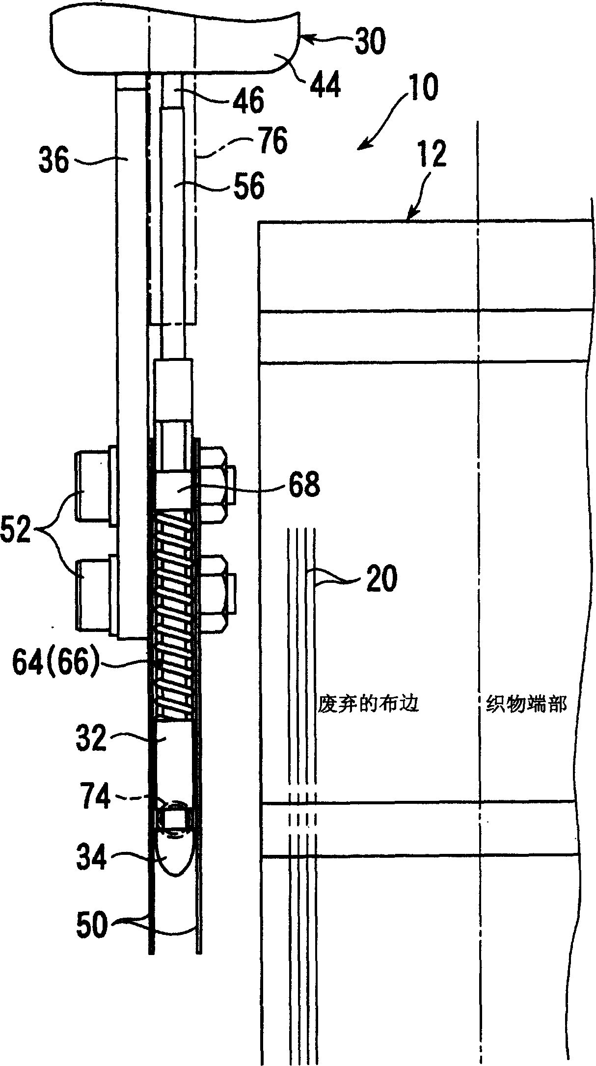
[0027] refer to Figure 1 ~ Figure 4 , the weft yarn holding device 10 is arranged on the anti-weft insertion side of the air jet loom, and performs weft insertion, and is used to hold the weft yarn 80 that is dropped into and advances to the cloth fell through the reed 12 (refer to Figure 4 ).

[0028] The weft yarn gripping device 10 is disposed on the reverse weft insertion side than the reed 12 that reeds the input weft yarn 80, and is detachably attached to a member different from the sley (not shown) by using the support arm 14. , For example, on the temple base 18 which rotatably supports the temple 16 . However, the installation position and installation state of the weft yarn gripping device 10 may be arbitrary as long as weaving and weft yarn gripping are not hindered.

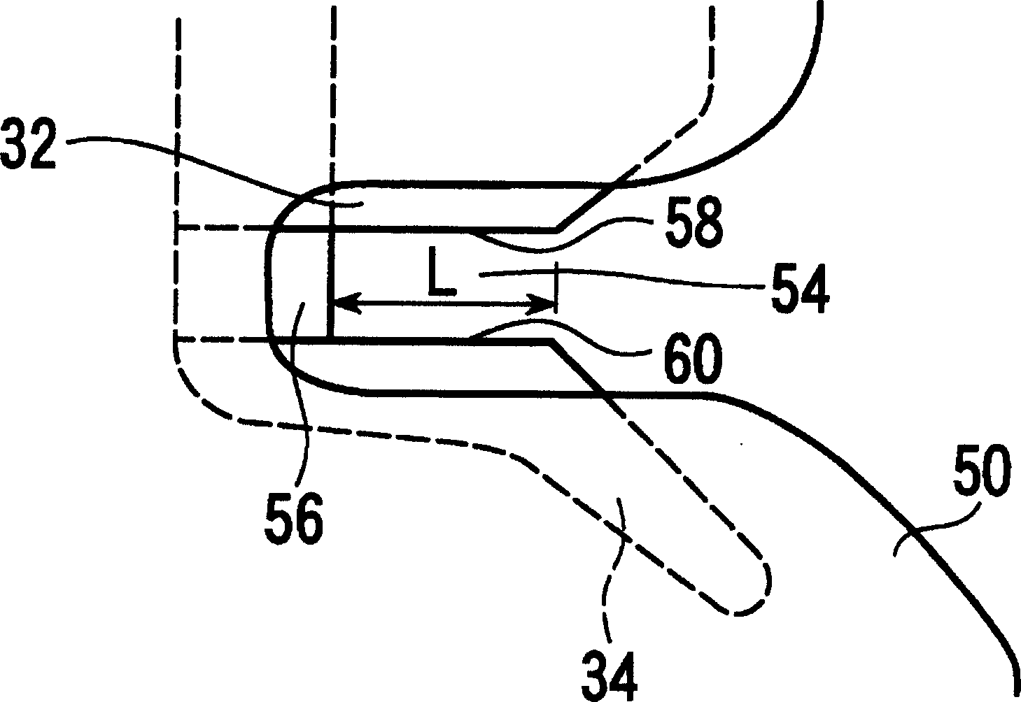
[0029] The reed 12 has a plurality of belt-shaped reed blades 20 at intervals in the fabric width direction. Each reed blade 20 has a convex portion 22 protruding toward the cloth fell side near ...


PUM


Abstract

Provided is a weft gripping device having high responsiveness to a grip order and surely gripping a weft. The weft gripping device 10 in a fluid-jet type loom comprises a pair of gripping members 32 and 34 which are a pair of the gripping members 32 and 34 having weft gripping parts 58 and 60 for receiving and gripping the weft 80 moving together with a reed 12 between the most advanced position and the most retreated position of the reed 12 and selectively and relatively moved in the contacting and separating directions of these members by a driving gear 30 and a latching member which latches the weft 80 received in the weft gripping parts 58 and 60 and positions the weft relatively to both the gripping members 32 and 34.

Description

technical field [0001] The invention relates to a weft yarn gripping device in a fluid jet loom, in particular to a weft yarn gripping device arranged on the reverse weft insertion side. Background technique [0002] As a weft gripping device in a fluid jet loom, techniques described in Japanese Patent Document 1 (JP-A-10-130999) and Japanese Patent Document 2 (JP-A-2000-199152) are known. [0003] In the prior art described in Japanese Patent Documents 1 and 2, one of a pair of gripping members gripping a weft yarn has a so-called hinge-like mechanism that rotates at a certain angle around a rotation axis. [0004] Also, in the two prior art, the length dimension of the weft yarn gripping portion, especially the length dimension of the portion that can be gripped when viewed from the weft insertion direction, exceeds the swing range of the reed (the distance between the most advanced position and the most advanced position of the reed). sco...

Claims


Application Information

Patent Timeline
IPC IPC(8): D03D47/28D03D47/30D03J1/04
CPCD03D47/308
Inventor 高桥荣利角谷和人泽田茂晴
Owner KAIHARA
Why Eureka
Try Eureka