Optical modulation device using vertical cavity laser array with electromechanical raster device

An array and grating technology, applied in the field of imaging and other light modulation devices, can solve the problems of different and complex spatial characteristics of modulated beams, and achieve the effects of high contrast, good light intensity and high resolution

Inactive Publication Date: 2004-05-19
EASTMAN KODAK CO
View PDF12 Cites 6 Cited by
  • Summary
  • Abstract
  • Description
  • Claims
  • Application Information

AI Technical Summary

Problems solved by technology

More notably, the spatial characteristics of the modulated beam can be relatively complex and different depending on whether out-of-phase or phase-locked modes of operation are employed

Method used


Image

  • Optical modulation device using vertical cavity laser array with electromechanical raster device
  • Optical modulation device using vertical cavity laser array with electromechanical raster device
  • Optical modulation device using vertical cavity laser array with electromechanical raster device

Examples


Embodiment Construction

[0034] The present detailed description refers to elements which form part of the apparatus of the invention or which cooperate more directly with the apparatus. It should be understood that elements not specifically shown or described may take various forms well known to those skilled in the art.

[0035] For the following description, components specific to the monochromatic light path can be more specifically identified by appending a letter next to the component number. Wherever used, letters correspond to color paths; for example, red is appended with an "r", blue with a "b", and green with a "g".

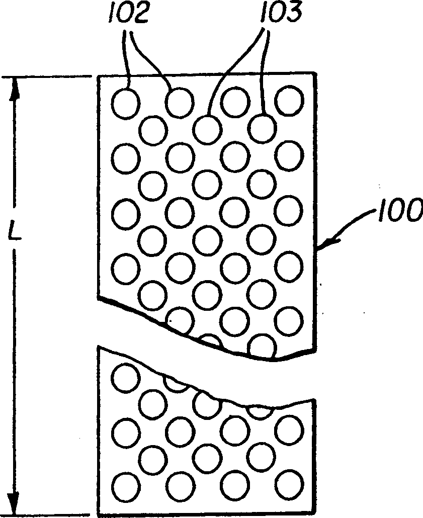
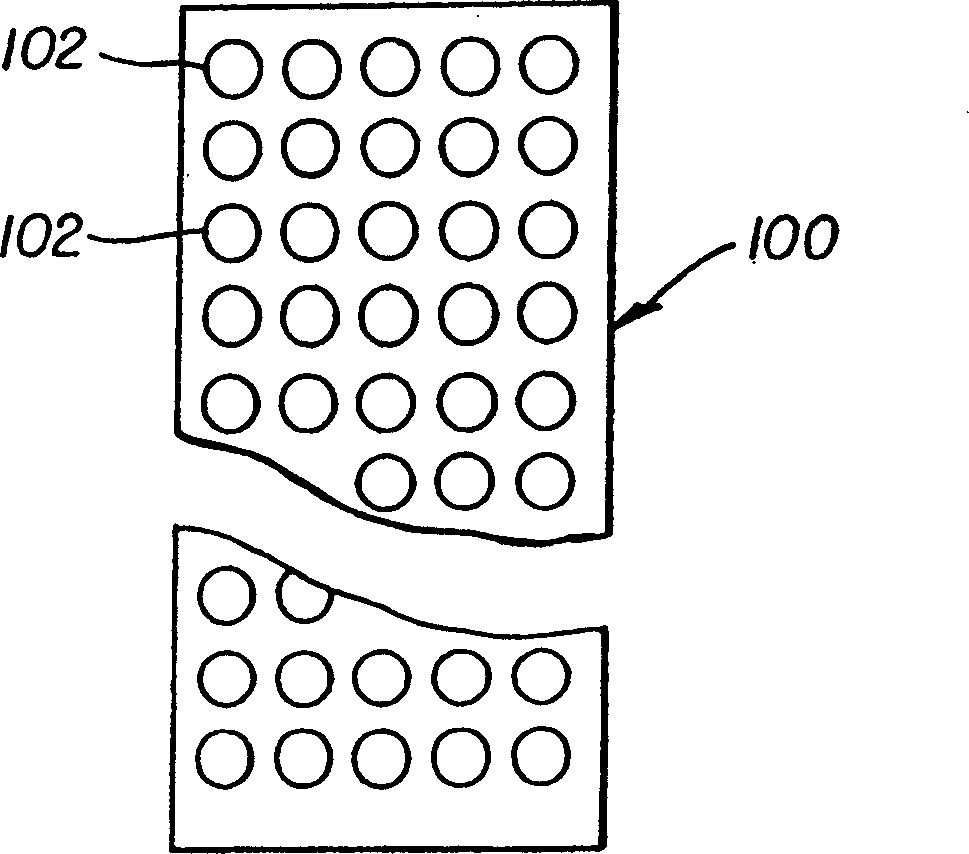
[0036] In the broadest embodiment, the device of the invention provides modulated light, one row at a time, with the light source being a VCSEL array and the light modulator being an electromechanical grating device. In the description that follows in this section, it is mainly directed to implementations such as imaging in printing and display devices. However, it is worth ...


PUM


Abstract

An apparatus for providing modulated light, that includes: a VCSEL array for generating an illumination beam from a plurality of emissive elements within the VCSEL array; a linear array of electromechanical grating devices for modulating the illumination beam to provide a plurality of diffracted orders; an obstructing element for blocking at least one of the plurality of diffracted orders; and means for conditioning the illumination beam to provide a suitable aspect ratio for incidence onto the linear array of electromechanical grating devices and / or remove unwanted spatial content.

Description

field of invention [0001] The present invention relates to imaging and other light modulation devices, and more particularly to an optical device for modulating light from an array of VCSELs and an array of electromechanical grating devices. Background technique [0002] Recent developments in digital imaging include the use of linear arrays as one-dimensional spatial light modulators. Images formed using a linear array are generated one line at a time, which is then scanned across a surface for display or printing. Linear arrays have been recognized to have some inherent advantages over two-dimensional liquid crystal displays (LCDs) and digital micromirror displays (DMDs) using areal spatial light modulators, including higher resolution, lower cost, and the ability to simplify illumination optics. In particular, where high color saturation, optimized color gamut, and good light intensity are emphasized, linear arrays of electromechanical grating devices are particularly s...

Claims


Application Information

Patent Timeline
Patent Type & Authority Applications(China)
IPC IPC(8): G02B5/18G02B26/08G02B26/10G02B26/12G02B27/09G02B27/44G03B21/14H01S3/00H01S5/183H01S5/42H04N3/08
CPCG02B26/0816G02B27/0916G02B26/0808H01S5/423G02B19/0052G02B19/0014H01S5/0085G02B26/08G02B26/12G02B27/0966G02B26/10G02B27/09G02B26/0883G02B27/0961
Inventor M·W·科瓦滋J·A·阿戈斯蒂内利K·B·卡肯
Owner EASTMAN KODAK CO
Why Eureka
Try Eureka