Driver of active luminous display panel

A light-emitting display, panel-driven technology, applied in static indicators, instruments, electrical components, etc., can solve the problems of complicated peripheral circuits and increased number of TFTs, etc.

Inactive Publication Date: 2004-05-26
TOHOKU PIONEER CORP
View PDF0 Cites 12 Cited by
  • Summary
  • Abstract
  • Description
  • Claims
  • Application Information

AI Technical Summary

Problems solved by technology

[0014] At the same time, in the case of using the above-mentioned voltage writing method, current writing method, or current mirror method, etc., in the case of an EL element lighting drive device, the problem that the number of TFTs constituting one pixel will increase. The arrangement of the signal lines for controlling these TFTs and the problem of complicating the peripheral circuits will occur

Method used


Image

  • Driver of active luminous display panel
  • Driver of active luminous display panel
  • Driver of active luminous display panel

Examples


Embodiment Construction

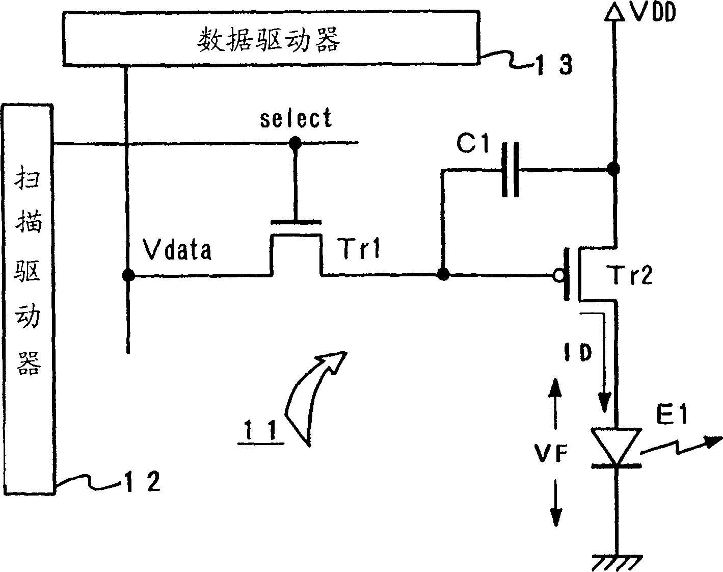
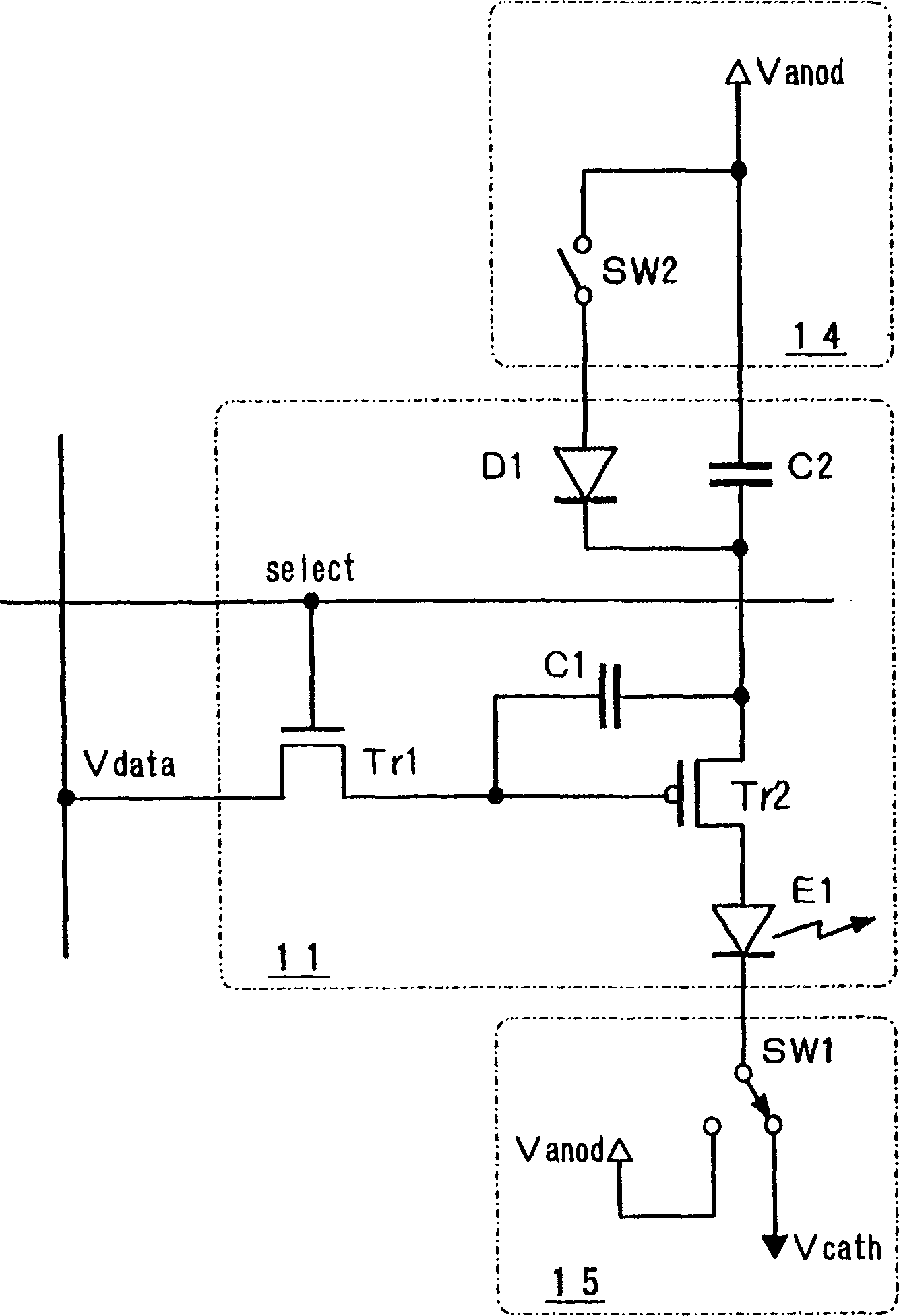
[0025] In the following, the light-emitting display panel driving device of the present invention will be described based on the illustrated embodiment. figure 2 Represents the first embodiment of the drive device including the pixel structure related to the present invention, in the pixel 11 and figure 1 As in the example shown, two TFTs including an N-channel control TFT (Tr1) and a P-channel drive TFT (Tr2) are included. Furthermore, between the gate and the source of the driving TFT (Tr2), a capacitor C1 for accumulating charges is connected, and at the same time, the anode of the EL element E1 as a light-emitting element is connected to the drain of the driving TFT (Tr2), In this way, a lighting drive circuit based on the conductance control method is constituted.

[0026] In addition, one end of the capacitor C2 for storing light emission power is connected to the source of the driving TFT (Tr2), and the other end of the capacitor C2 is connected to the voltage source ...


PUM


Abstract

In order to provide, as a lighting means for a pixel including a driving TFT and an EL element, a driving device of a light emitting display panel which can dissolve respective technical problems which occur in cases where respective constant voltage driving and constant current driving techiniques are adopted, a light emitting power holding capacitor (C2) is connected in series to the driving TFT (Tr2) and the EL element (E1). A diode (D1) for charging electrical charges in the capacitor (C2) and a switching element (SW2) for supplying current to the diode (D1) are provided. By an ON operation of the switching element (SW2) both ends of the capacitor (C2) is subjected to a charge operation so as to become equipotentials. By an OFF operation of the switching element (SW2), driving current flows in the EL element (E1) via the driving TFT (Tr2). The amount of current flowing in the EL element (E1) is controlled by the repeat frequency of ON/OFF of the switching element (SW2).

Description

technical field [0001] The present invention relates to a light-emitting display panel driving device that actively drives light-emitting elements constituting a pixel by TFT (Thin Film Transistor), and particularly relates to a light-emitting display panel in which a driving power supply device for supplying driving power to light-emitting elements is improved. drive unit. Background technique [0002] The development of a display using a display panel configured by arranging light-emitting elements in a matrix has been widely advanced. As a light-emitting element used in such a display panel, an organic EL (electroluminescence) element using an organic material for a light-emitting layer has attracted attention. This also depends on the background that, in the light-emitting layer of the EL element, high efficiency and long life in practical use have been achieved by using organic compounds that are expected to have good light-emitting characteristics. [0003] As a disp...

Claims


Application Information

Patent Timeline
Patent Type & Authority Applications(China)
IPC IPC(8): H01L51/50G09G3/20G09G3/30G09G3/32
CPCG09G2300/0852G09G2320/043G09G2310/0262G09G2300/0809G09G3/2018G09G2320/0233G09G3/3233G09G2320/04G09G2310/0256G09G3/3291G09G3/30
Inventor 关修一
Owner TOHOKU PIONEER CORP
Why Eureka
Try Eureka