Hydraulic screw nut disengaging device

A nut and hydraulic technology, applied in the field of hydraulic nut breaker, can solve the problems of difficult disassembly and inconvenient use, and achieve the effect of simple operation and convenient use

Inactive Publication Date: 2004-06-16
上海神模电气有限公司
View PDF0 Cites 5 Cited by
  • Summary
  • Abstract
  • Description
  • Claims
  • Application Information

AI Technical Summary

Problems solved by technology

[0003] The technical problems to be solved by the present invention are: 1. When the nut is corroded and killed, the existing dismounting tool is completely dependent on manpower, and it is difficult to complete the disassembly operation; 2. There are too many types of nuts, and one kind of nut corresponds to one kind of nut. Special disassembly tool, very inconvenient to use

Method used


Image

  • Hydraulic screw nut disengaging device
  • Hydraulic screw nut disengaging device

Examples


Embodiment Construction

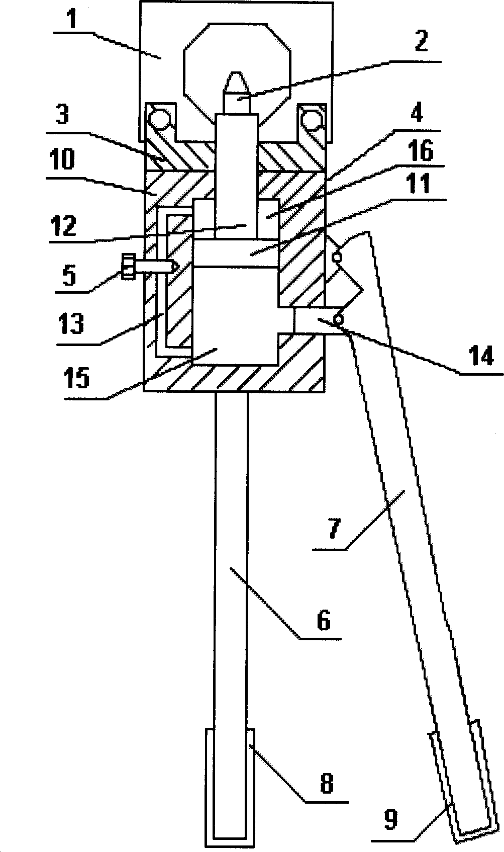
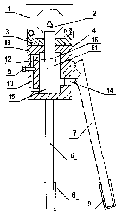
[0007] Such as figure 1 As shown, the hydraulic nut breaker of the present invention consists of a pressure head 1, a top 2, a pliers head 3, a hydraulic pump 4, an oil return nut 5, a fixed handle 6, a movable handle 7, a fixed grip 8 and a movable grip 9 Composition, the described indenter 1 is provided with a central hole, the shape of the described central hole can be a regular hexagon, one end of the described indenter 1 is provided with a slit, and the two sides of the indentation of the described indenter Connect with one end of the pliers head 3, the specific connection method can be a screw connection, a circular through hole is arranged on the axial centerline of the pliers head 3, and the pliers head 3 and the hydraulic pump 4-phase connection, the specific connection method can be welding connection, the hydraulic pump 4 is composed of a pump body 10, a piston 11, a piston rod 12, an oil return line 13, a small piston 14, an oil storage chamber 15 and an oil pressu...


PUM


Abstract

The invention relates to a hydraulic screw cap opener which comprises a pressure head, a finial, a binding clip, a hydraulic pump, an oil return screw nut, a fixed handgrip, a movable handgrip, a fixed lever and a movable lever. Compared with the prior art, by using the hydraulic screw cap opener, the invention can be used for dismounting various types of screw caps with easiness in use and simple operation.

Description

Technical field: [0001] The invention relates to a manual removal tool, in particular to a hydraulic nut breaker for removing nuts. Background technique: [0002] In the existing technology, the nuts are prone to corrosion and seizure, which makes the disassembly of the nuts very difficult. The method usually used now is to use ordinary special nut removal tools, and one type of nut corresponds to a special The disassembly tool is very inconvenient to use. When the nut is corroded and killed, it cannot be disassembled completely by manpower. Invention content: [0003] The technical problems to be solved by the present invention are: 1. When the nut is corroded and killed, the existing dismounting tool is completely dependent on manpower, and it is difficult to complete the disassembly operation; 2. There are too many types of nuts, and one kind of nut corresponds to one kind of nut. The special disassembly tool is very inconvenient to use. [0004] The technical solutio...

Claims


Application Information

Patent Timeline
Patent Type & Authority Applications(China)
IPC IPC(8): B25B27/14
Inventor 祝志斌
Owner 上海神模电气有限公司
Why Eureka
Try Eureka