Structure for disposing fuel system in motor

A technology for fuel systems and motorcycles, applied to motorcycles, charging systems, and panniers on bicycles, etc., can solve problems such as narrowing degrees of freedom, and achieve the effects of increasing degrees of freedom, smooth layout, and good appearance

Active Publication Date: 2004-06-16
HONDA MOTOR CO LTD
View PDF1 Cites 8 Cited by
  • Summary
  • Abstract
  • Description
  • Claims
  • Application Information

AI Technical Summary

Problems solved by technology

[0003] However, in the structure in which the fuel pump is installed on the upper wall of the fuel tank, the connecting portion of the fuel pump and the fuel hose must be arranged on the upper wall of the fuel tank. Interfering with this connecting portion, in the above-mentioned conventional structure, the height of the seat for riding is set at a position that does not interfere with the connecting portion, so that the height of the seat for riding is set. degrees of freedom are narrowed

Method used


Image

  • Structure for disposing fuel system in motor
  • Structure for disposing fuel system in motor
  • Structure for disposing fuel system in motor

Examples


Embodiment Construction

[0032] Hereinafter, embodiments of the present invention will be described with reference to embodiments of the present invention shown in the drawings.

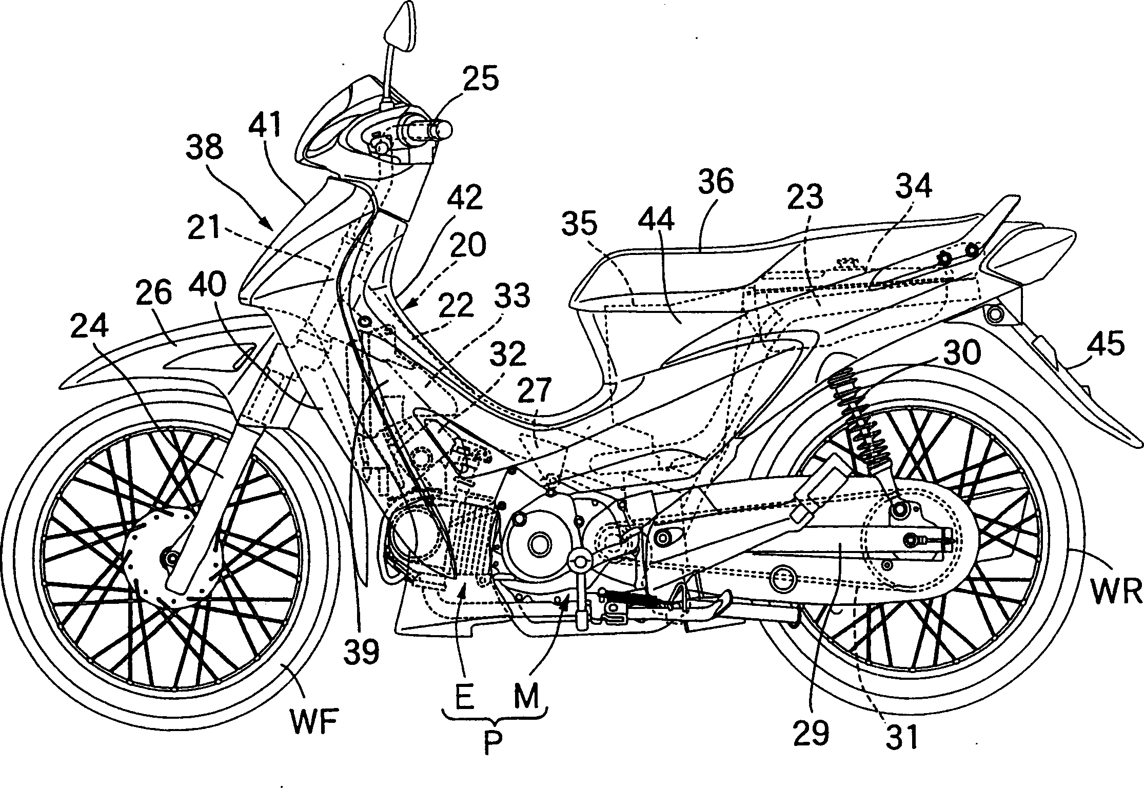
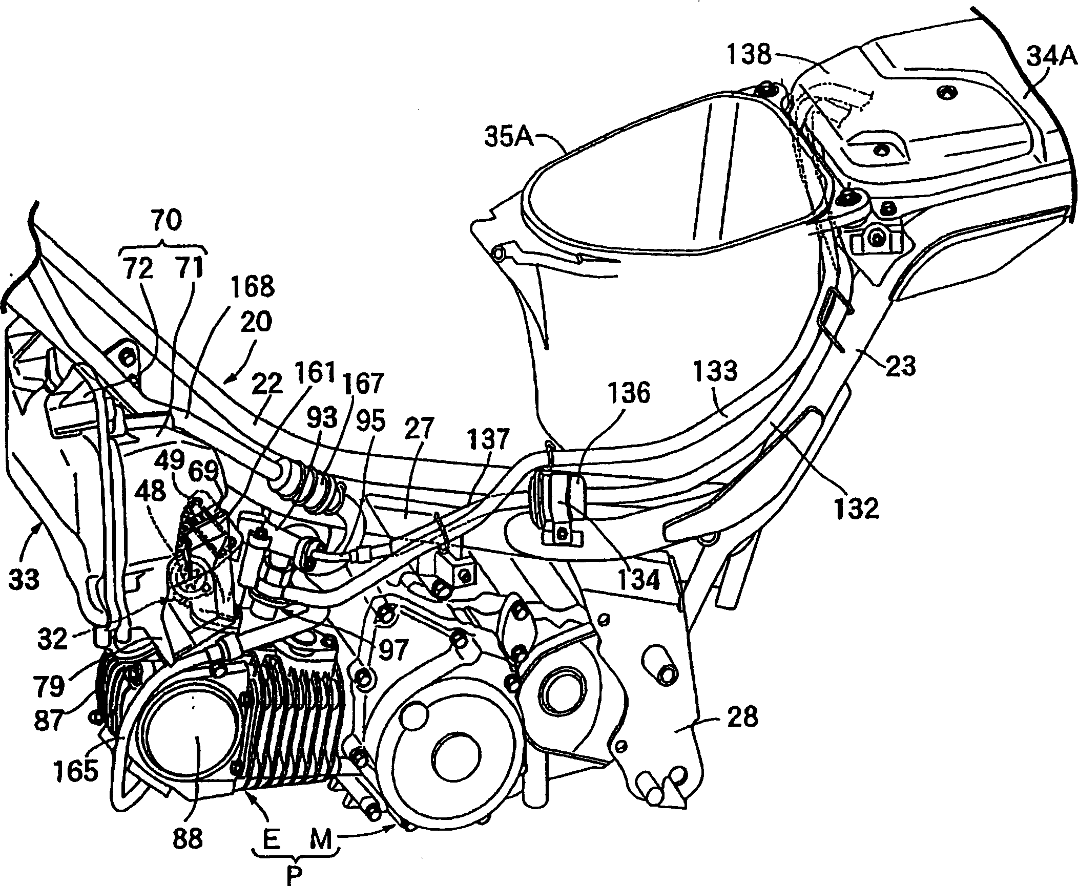
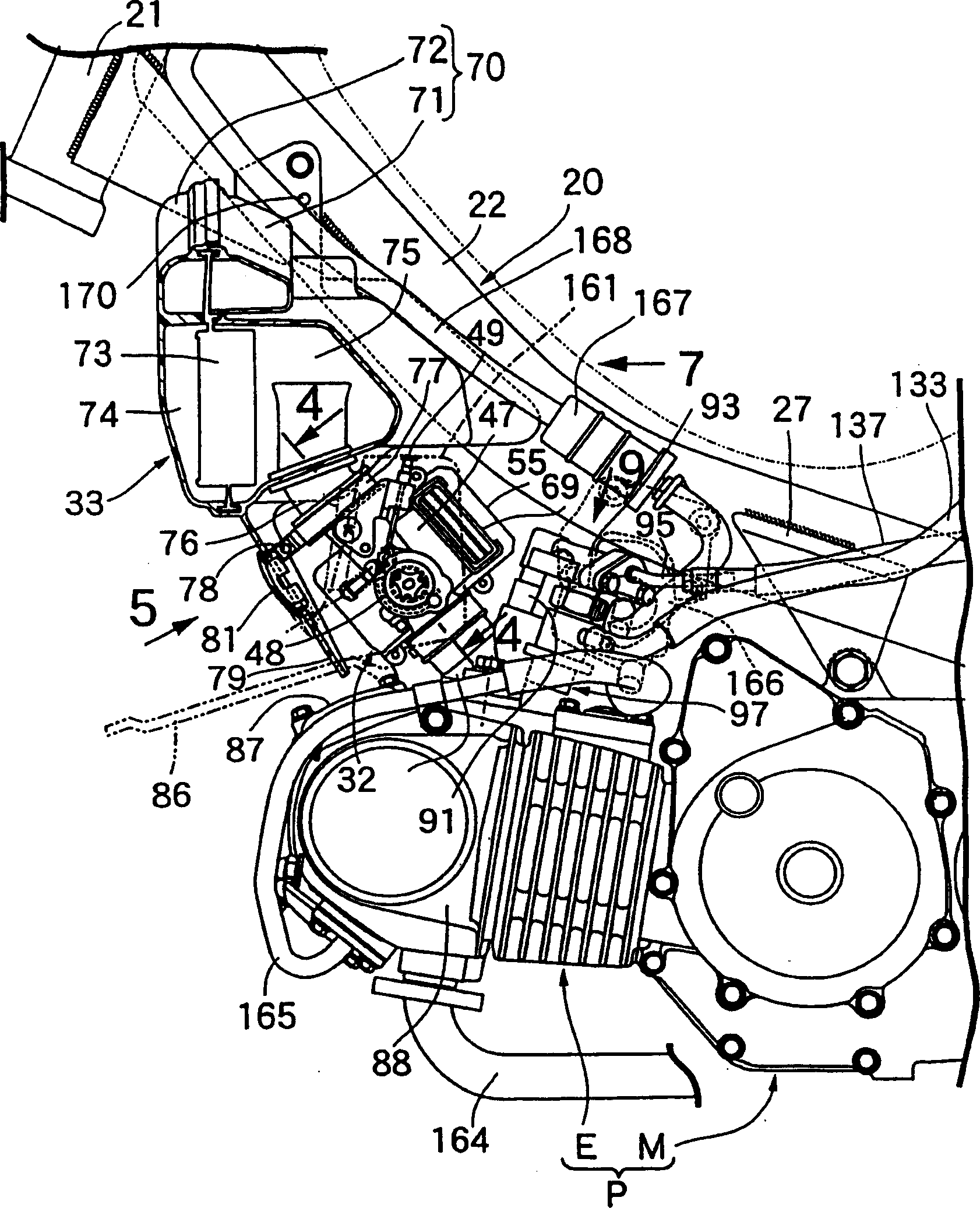
[0033] Figure 1 to Figure 18 shows an embodiment of the present invention. figure 1 is a side view of the motorcycle as a whole; figure 2 It is a perspective view of the central part of the motorcycle in the front-rear direction with the body cover removed; image 3 is a side view of the engine and air intake system; Figure 4 is along image 3 The enlarged cross-sectional view of line 4-4 in Figure 5 is along image 3 The enlarged view of arrow 5 in ; Image 6 is along Figure 5 Sectional drawing of line 6-6 in Figure 7 From image 3 The rear view of the air filter viewed in the direction of arrow 7; Figure 8 is along Figure 7 Sectional drawing of line 8-8 in Figure 9 is along image 3 The arrow 9 in the view; Figure 10 is the plan view of the intake pipe and fuel injection valve; Figure 11 is along ...


PUM


Abstract

To prevent the interference of a riding seat with a connection part to a fuel pump while increasing the freedom degree of setting of the height of the riding seat in a motorcycle wherein the fuel pump attached on the upper wall of a fuel tank is housed in the fuel tank mounted on a vehicle frame, and an upper part of the fuel tank is covered by the riding seat.The fuel pump 118 is attached on a pump attachment part 119 downward recessed and provided on the upper wall of the fuel tank 34, and the pump attachment part 119 is covered by a cover 138 from an upper part.

Description

technical field [0001] The present invention relates to a motorcycle in which a fuel pump mounted on an upper wall of a fuel tank is accommodated in a fuel tank mounted on a vehicle frame, and a seat for riding is covered above the fuel tank, in particular, The invention relates to an improvement in the structure for arranging a fuel system on a motorcycle. Background technique [0002] A motorcycle in which a seat for riding is covered over a fuel tank housing a fuel pump is known, for example, as disclosed in Patent Document 1, ie, Japanese Patent Publication No. Hei 7-110630. [0003] However, in the structure in which the fuel pump is installed on the upper wall of the fuel tank, the connecting portion of the fuel pump and the fuel hose must be arranged on the upper wall of the fuel tank. Interfering with this connecting portion, in the above-mentioned conventional structure, the height of the seat for riding is set at a position that does not interfere with the connect...

Claims


Application Information

Patent Timeline
Patent Type & Authority Applications(China)
IPC IPC(8): B62J37/00B62J1/12B62J9/00B62J35/00B62K11/04B62K25/20F02M37/00
CPCB62J1/12B62J9/40B62J35/00B62J37/00
Inventor 山口正昭与仓康文梅泽尚司
Owner HONDA MOTOR CO LTD
Why Eureka
Try Eureka