Hand held apparatus having sleep function and operating method thereof

The technology of a handheld device and operation method is applied in the direction of data processing power supply, etc., which can solve the problems of delaying data loss, increasing user costs, cumbersome operation, etc., and achieves the best handheld device function, prolonging the use time, and long standby time the effect of time

The technology of a handheld device and operation method is applied in the direction of data processing power supply, etc., which can solve the problems of delaying data loss, increasing user costs, cumbersome operation, etc., and achieves the best handheld device function, prolonging the use time, and long standby time the effect of time

CN1504859AInactive Publication Date: 2004-06-16ACER INC

Image

  • Hand held apparatus having sleep function and operating method thereof
  • Hand held apparatus having sleep function and operating method thereof
  • Hand held apparatus having sleep function and operating method thereof

Examples


Embodiment Construction

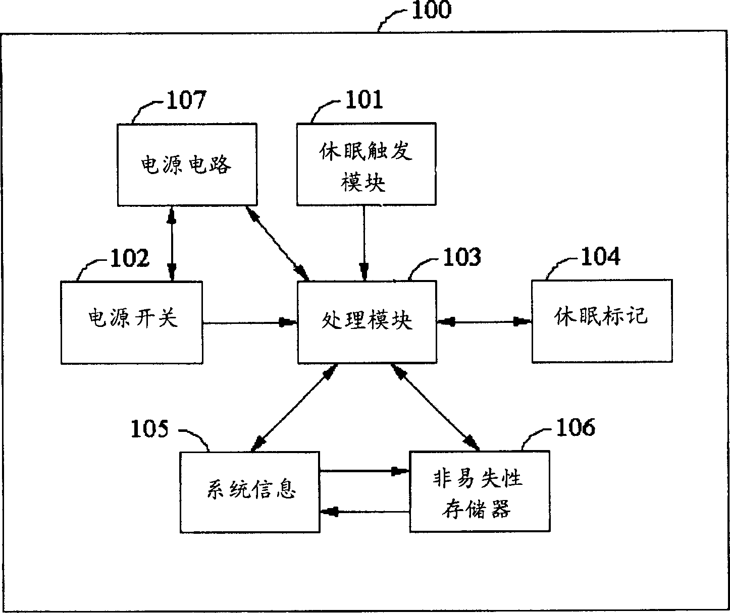
[0036] figure 1 A system architecture of a handheld device with sleep function according to an embodiment of the present invention is shown. The handheld device 100 with sleep function according to the embodiment of the present invention has a sleep trigger module 101 , a power switch 102 , a processing module 103 , a sleep flag 104 , a system information 105 , and a non-volatile memory 106 .

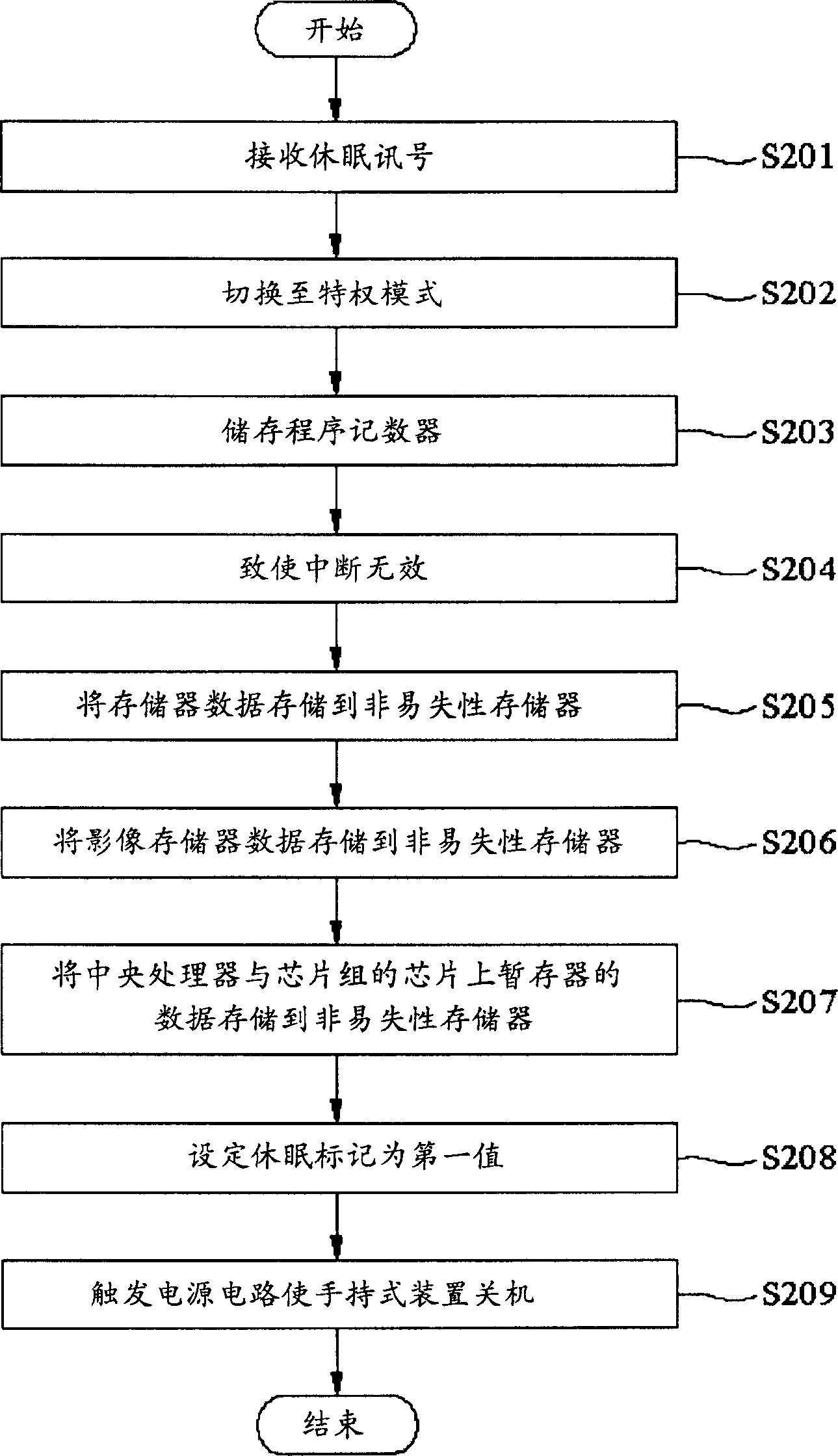
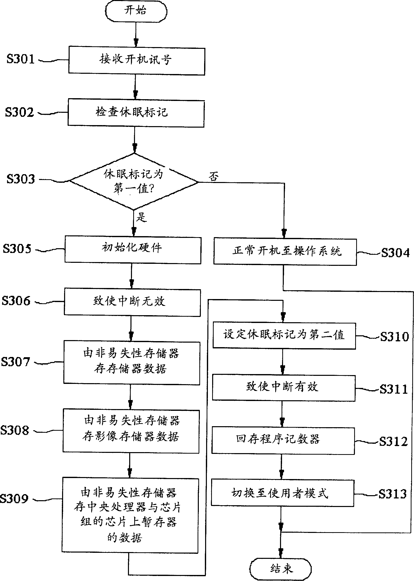
[0037] The sleep trigger module 101 can be a button set on the handheld device 100 or a software program on the handheld device 100. The sleep trigger module 101 is used to receive a sleep signal, thereby causing the handheld device 100 to enter a sleep state. In addition, the power switch 102 is used to receive a power-on signal, so as to cause the handheld device 100 to boot into the operating system in a normal way or return from the sleep state to the system state before the handheld device 100 enters the sleep state.

[0038] The sleep flag 104 is used to record the state of the h...


PUM


Abstract

The hand-held apparatus having dormancy function comprises a dormancy triggering module for receiving a dormancy signal, a dormancy mark, a non-volatile memory and a processing module, wherein the processing module responds the dormancy signal and switches the hand-held device to privileged mode, the system information of hand-held apparatus is stored to the non-volatile memory, while the dormancy mark is labeled as a first value, and a power supply circuit is triggered to shut down the hand-held apparatus.

Description

technical field [0001] The present invention relates to a handheld device (Handheld Device) with sleep function and its operating method, and particularly relates to a method of transferring system information of the handheld device by triggering the hardware abstraction layer (Hardware Abstraction Layer, HAL) of the handheld device. The hand-held device and its operating method are stored in a non-volatile memory, thereby causing the hand-held device to enter a dormant state, so as to actually achieve the purpose of saving power. Background technique [0002] With the popularization of mobile communication, handheld devices, such as handheld computers (Handheld PC), personal digital assistants (Personal Digital Assistant, PDA), etc., have become one of the necessities in most people's lives. For existing handheld devices, when the user presses the on / off button on the handheld device, the screen of the handheld device will be turned off, and when the user presses the on / off...

Claims


Application Information

Patent Timeline
16 Jun 2004
Publication
CN1504859A
IPC
G06F1/32
Inventors
陈永春; 陈松柏