Method and apparatus for controlling zone operating of elevator equipment

A technology for controlling partitions and elevators. It is used in transportation and packaging, elevators, etc., and can solve problems such as inability to achieve capacity and increase.

Active Publication Date: 2004-06-23
INVENTIO AG
View PDF1 Cites 14 Cited by
  • Summary
  • Abstract
  • Description
  • Claims
  • Application Information

AI Technical Summary

Problems solved by technology

However, taking this measure will not achieve a significant increase in capacity

Method used


Image

  • Method and apparatus for controlling zone operating of elevator equipment
  • Method and apparatus for controlling zone operating of elevator equipment
  • Method and apparatus for controlling zone operating of elevator equipment

Examples


Embodiment Construction

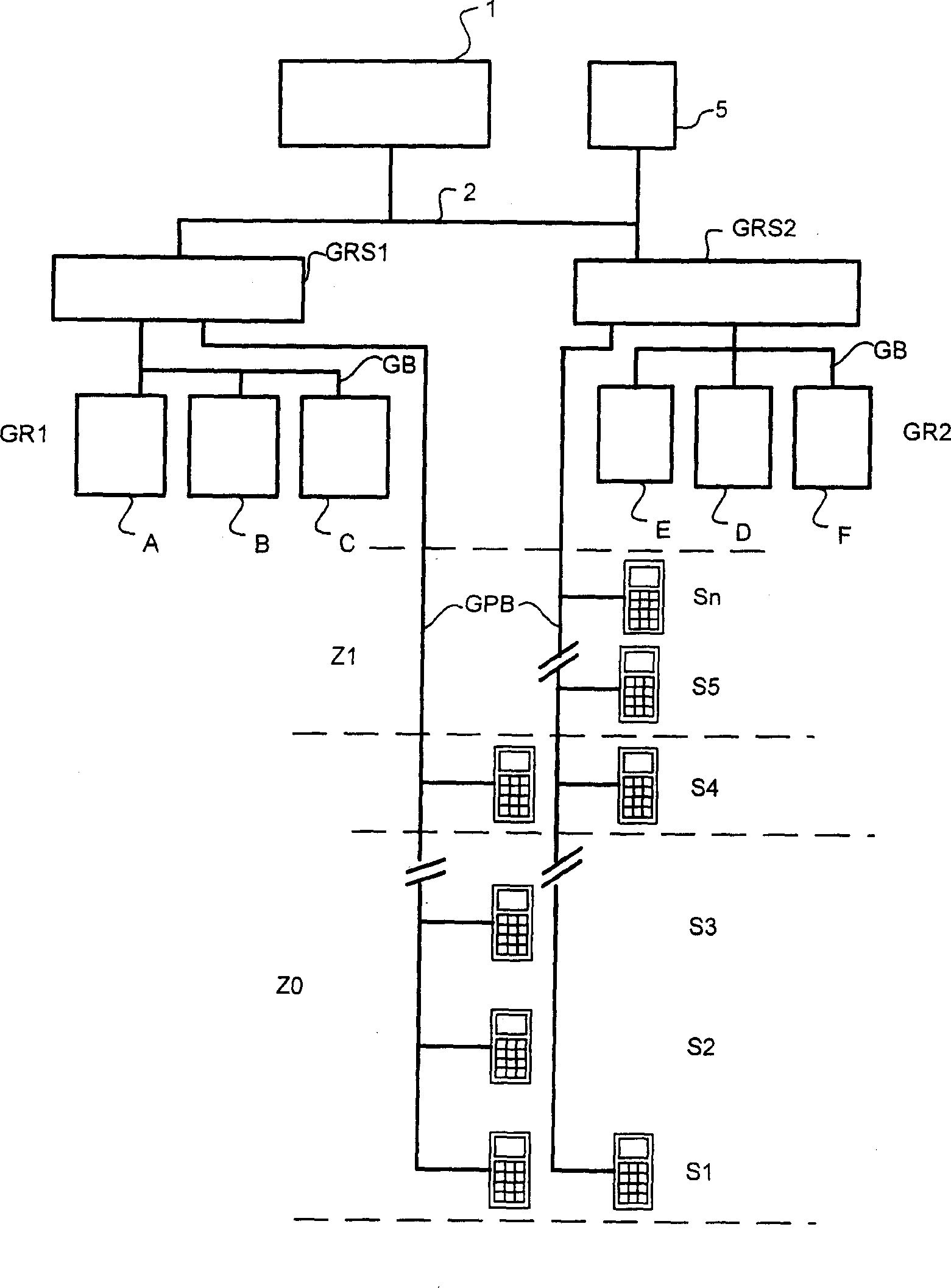
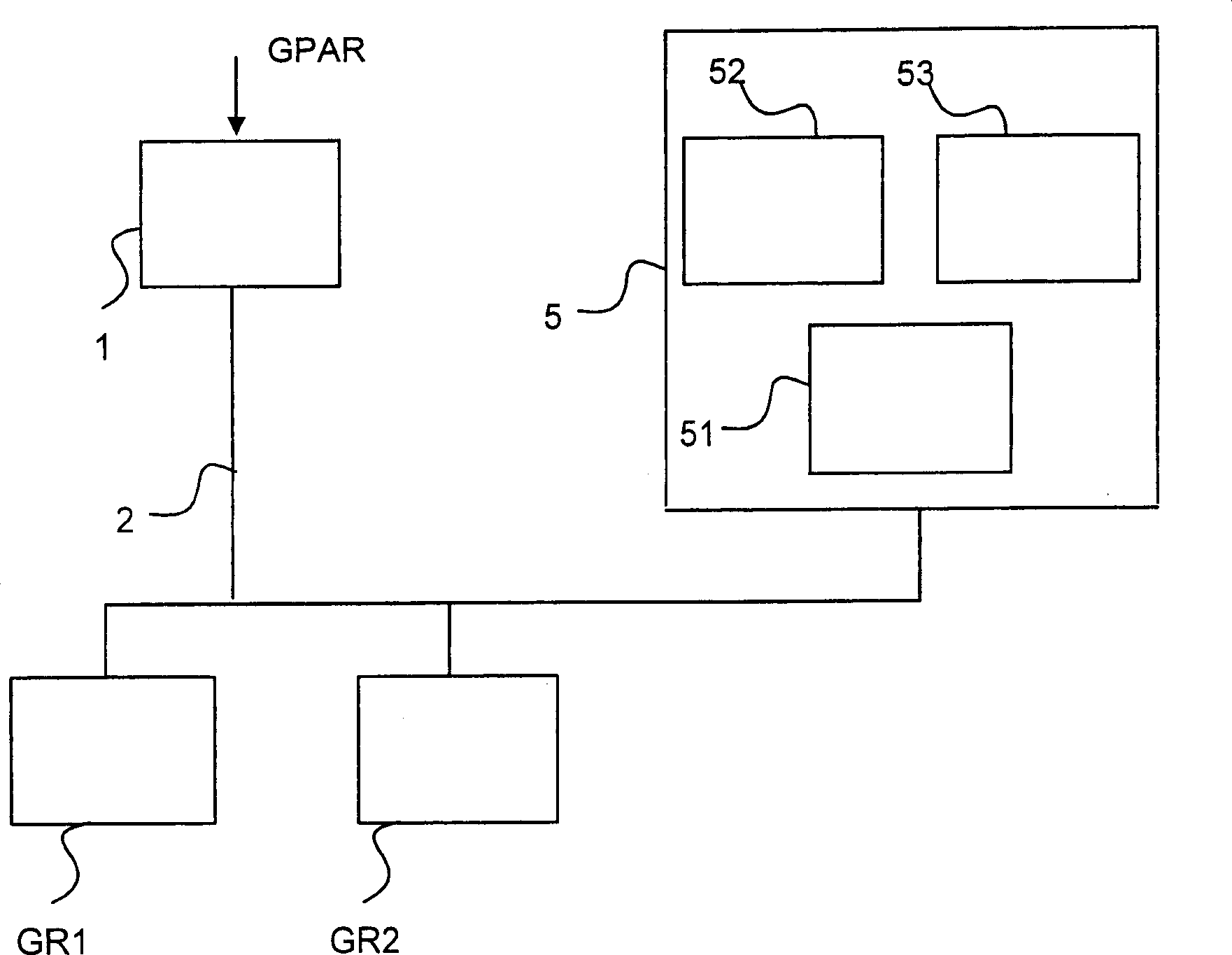
[0026] figure 1 It is a schematic diagram of the structure of the elevator equipment. The building is divided into zones Z1, Z0. Each zone has multiple floors. The zone Z0 includes floors S1 to Sn. Elevators A-F are used to transport passengers within these zones. The elevators A-F are divided into elevator groups GR1 and GR2. The elevator is controlled via a destination call controller ZEG (not shown). Elevator group GR1 transports passengers in zone Z0 from floor S1 to S4, and GR2 transports passengers in zone Z1 from floor S4 to Sn. In this case, elevator group GR1 can also be used to reach floor S1. The group control unit GRS1 of the first elevator group controls the elevator group GR1 and the control unit GRS2 of the second elevator group controls the elevator group GR2. The elevators are each connected to the group control units GR1 and GR2 via a group bus GB. Each floor is connected to the group control unit through a group external bus GPB. A multigroup contro...


PUM


Abstract

A method for controlling a zonally operated elevator installation, wherein on a changeover floor changing between zones is made possible, and wherein with a delivering elevator group and a collecting elevator group transportation to and from the changeover floor is realized, and wherein a trip destination is entered via a destination-call control by each passenger to be transported. An elevator installation for zonal operation in buildings with several elevators, wherein each elevator group contains at least one destination-call input device for registering the destination of a passenger. Each elevator is assigned to an elevator group, the building is divided into zones, and a changeover floor for changing between the elevator groups is arranged between the zones. The delivering elevator group and the collecting elevator group are combined into a multi-group which is controlled by a multi-group control.

Description

technical field [0001] The invention relates to a method for controlling an elevator system operating in zones, in which a transfer between zones is possible at a transfer floor and in which a drive to or drive to is carried out on this floor with an approaching elevator group and an departing elevator group The transfer from the transfer floor is carried out and the destination floor is entered by each transported passenger via the destination floor control unit. In addition, the invention relates to an elevator installation with a plurality of elevators operating in zones in a building, wherein each elevator group contains at least one destination call input device for collecting data on the destination floors of passengers, and each elevator is assigned to a elevator groups, and the building is divided into zones and a transfer floor is provided between the zones for transferring between the elevator groups. Background technique [0002] Intelligent elevator control unit...

Claims


Application Information

Patent Timeline
Patent Type & Authority Applications(China)
IPC IPC(8): B66B1/20
CPCB66B1/20
Inventor 米洛斯洛夫·科斯卡库尔特·施泰因曼
Owner INVENTIO AG
Why Eureka
Try Eureka