
Electronic element and its manufacturing method

A technology of electronic components and manufacturing methods, which is applied in the direction of electrical components, electric solid devices, circuits, etc., and can solve problems such as cracking of the sealing cover and reduction of the mechanical strength of the sealing cover

Inactive Publication Date: 2004-06-30
MURATA MFG CO LTD
View PDF0 Cites 7 Cited by
  • Summary
  • Abstract
  • Description
  • Claims
  • Application Information

AI Technical Summary

Problems solved by technology

However, when the thickness of the sealing cover is reduced, the mechanical strength of the sealing cover is also reduced
Therefore, during the manufacturing process, the sealing cap is often broken

Method used


Image

  • Electronic element and its manufacturing method
  • Electronic element and its manufacturing method
  • Electronic element and its manufacturing method

Examples


Embodiment Construction

[0035] Preferred embodiments of the present invention will be described in detail below with reference to the accompanying drawings.

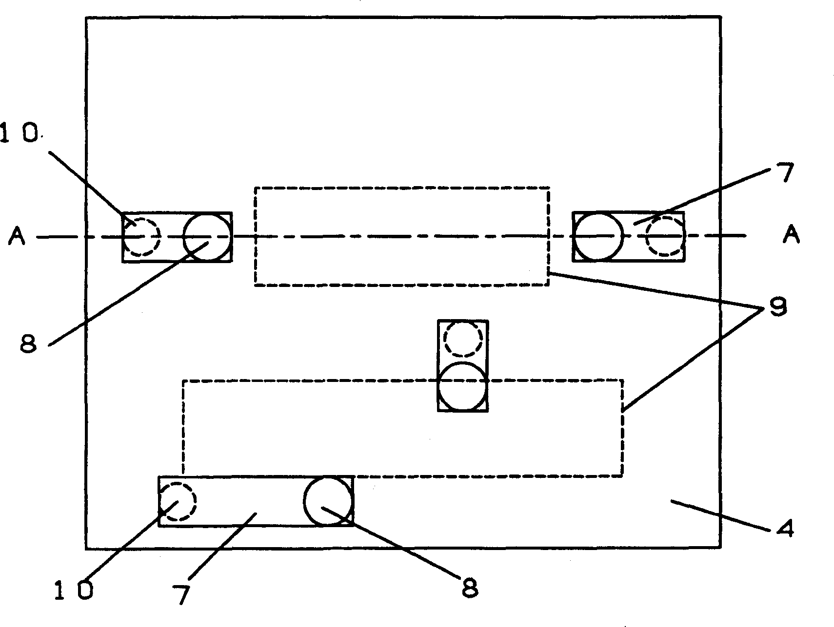
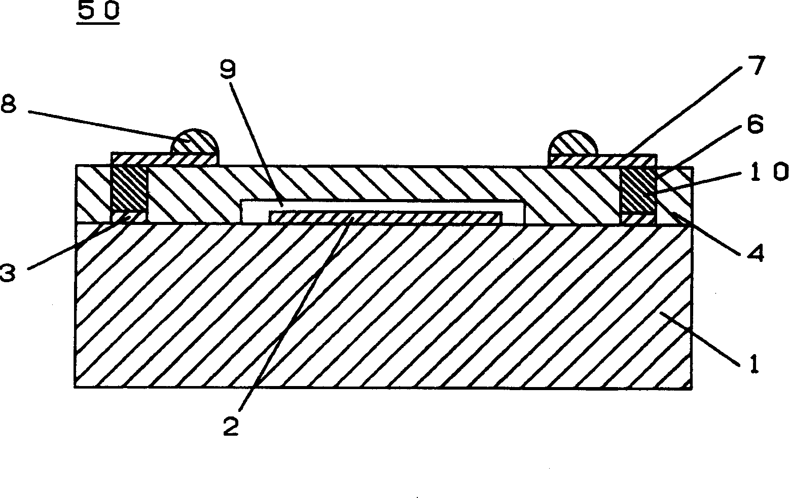
[0036] figure 1 is a schematic plan view of an electronic component of a preferred embodiment of the present invention. figure 2 is along figure 1 Sectional view taken along line A-A.

[0037] Refer to the following figure 1 and 2 , an electronic component 50 includes a substrate 1 and a structural component 4 .

[0038] A plurality of IDT electrodes 2 and connection portions 3 are provided on the substrate 1 . Each connection portion 3 is electrically connected to the IDT electrode 2 . In order to achieve the desired function. In addition, electrodes are provided on each IDT electrode 2, and these electrodes have various patterns and film thicknesses suitable for required functions. The respective patterns are not limited to the IDT electrodes 2 . These patterns can also be applied to electrodes defining piezoelectric vibrating porti...


PUM


Abstract

An electronic component includes at least one piezoelectric vibrating portion, a connecting portion provided on a substrate, a structural piece including a concavity so as not to disturb the vibration of the piezoelectric vibrating portion, and a connecting wiring for electrically connecting a pad on the substrate to a mounting wiring disposed on the upper surface of the structural piece. The structural piece further includes a through hole having an electro-conductive material filled therein. The structural piece seals the piezoelectric vibrating portion.

Description

technical field [0001] The present invention relates to an electronic component used for electronic circuits in the communication field such as a portable telephone or television, comprising at least one piezoelectric vibrating portion and a connecting portion provided on a substrate. Background technique [0002] The basic structure of such electronic components includes a piezoelectric vibrating portion provided on a substrate, and the piezoelectric vibrating portion is accommodated in a hermetically sealed package in order to ensure its reliability. [0003] The space included in a portion of the package corresponding to the upper surface of the piezoelectric vibrating portion allows unhindered vibration of the piezoelectric vibrating portion provided on the substrate. Packages made of metal or ceramics are used to ensure reliability. However, the above structure increases the size of the package. This hinders size reduction of electronic components. [0004] Moreover,...

Claims


Application Information

Patent Timeline
Patent Type & Authority Applications(China)
IPC IPC(8): H01L23/02H01L23/04H03H3/02H03H3/08H03H9/02H03H9/10H03H9/25
CPCH03H9/1092H03H9/059H01L2224/11H01L2224/05008H01L2224/05026H01L2224/0508H01L2224/05568H01L2224/05023H01L2224/05001H01L2224/05569H01L2224/05548H01L2224/05624H01L2924/00014H01L2224/05644H01L2224/05647H01L2224/05655H01L2224/05144H01L2224/05147H01L2224/05124H01L2924/01029H01L2924/013H01L2224/05111
Inventor 岩本敬
Owner MURATA MFG CO LTD
Learn More