Porous pipe and pipe connector, manufacturing method thereof

A manufacturing method and technology of porous pipes, applied in the direction of pipes/pipe joints/fittings, pipes, rigid pipes, etc., can solve the problems of material waste, uneconomical cost, etc., to save materials, save material costs, and increase anti-aging strength Effect

Inactive Publication Date: 2004-07-07
罗德良
View PDF0 Cites 10 Cited by
  • Summary
  • Abstract
  • Description
  • Claims
  • Application Information

AI Technical Summary

Problems solved by technology

This will cause unnecessary waste of materials, and the cost is also very uneconomical.

Method used


Image

  • Porous pipe and pipe connector, manufacturing method thereof
  • Porous pipe and pipe connector, manufacturing method thereof
  • Porous pipe and pipe connector, manufacturing method thereof

Examples


Embodiment 1

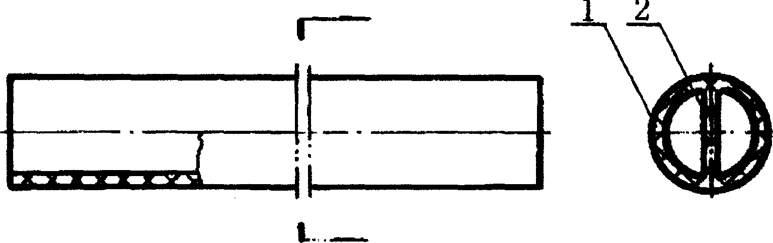
[0029] Embodiment 1, by figure 1 It can be seen that the inner cavity of the tube diameter of the present invention is provided with a reinforced isolation rib 2 passing through the center of the tube diameter to divide the inner cavity of the tube into two passages.

Embodiment 2

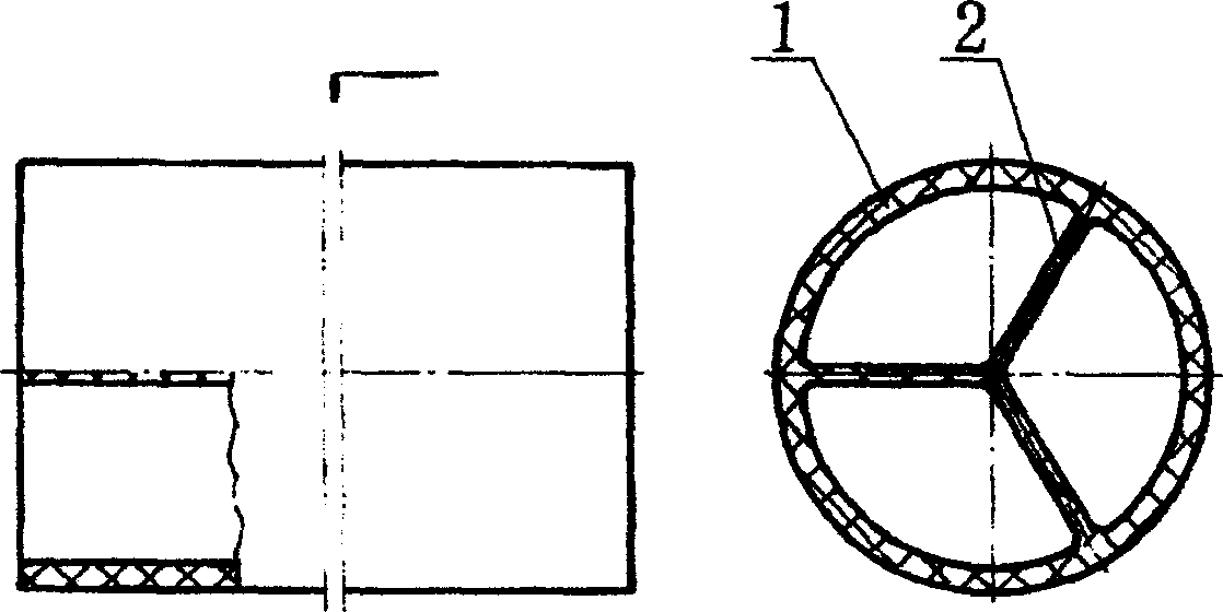
[0030] Embodiment 2, by figure 2 It can be seen that the inner cavity of the tube diameter of the present invention is provided with three reinforced isolation ribs 2 connected at the center of the tube diameter to divide the inner cavity of the tube equally into three channels.

Embodiment 3

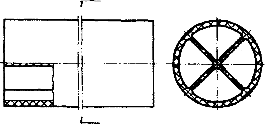
[0031] Embodiment 3, by image 3 It can be seen that the inner cavity of the tube diameter of the present invention is provided with two reinforced isolation ribs 2 crossing through the center of the tube diameter to divide the inner cavity of the tube equally into four channels.


PUM


Abstract

A multi-hole pipe features that more reinforcing and isolating ribs fixed to pipe wall are arranged in internal cavity of pipe to divide the pipe cavity into more than two channels. A multi-hole pipe jointer has also said reinforcing and isolating ribs. Its advantage is its improved rigidity and strength.

Description

Technical field [0001] The invention relates to a pipe material, a pipe fitting and a manufacturing method. Background technique [0002] At present, from foreign countries to China, from the introduction of materials and what we encounter in our daily life, no matter it is a metal pipe or an engineering plastic pipe for short, the inner diameter is all single-hole, but there are still many shortcomings for large pipes, such as For liquid pipes and gas pipes with large inner diameters, the larger the cross-sectional area, the greater the total pressure due to the large unit pressure, and the corresponding increase in the ring stress. The pipes must bear a certain huge pressure, so the wall thickness of the pipe diameter is also corresponding To thicken, because the outer diameter is fixed, the pipe wall is thickened, on the contrary, the inner diameter is reduced, the inner diameter is reduced, and the flow rate is also reduced. This causes unnecessary waste of materials, a...

Claims


Application Information

Patent Timeline
Patent Type & Authority Applications(China)
IPC IPC(8): B29C48/32F16L9/12
Inventor 罗德良
Owner 罗德良
Why Eureka
Try Eureka