
Differential/pressure transmitter

A transmitter, pressure technology, applied in the direction of measuring fluid pressure, pressure difference measurement between multiple valves, instruments, etc., can solve the increase in the number of types of caps or adapters, cannot meet customer requirements, and the results cannot be shipped after transportation. changes, etc.

Active Publication Date: 2004-07-14
YAMATAKE HONEYWELL CO LTD
View PDF2 Cites 7 Cited by
  • Summary
  • Abstract
  • Description
  • Claims
  • Application Information

AI Technical Summary

Problems solved by technology

[0014] If the shape of the pressure guide cap is changed according to the shape of the pipe, or a dedicated adapter is used, the number of types of caps or adapters increases, and as a result, changes cannot be made after transportation
If you do not prepare spare caps and adapters, you cannot meet customer requirements

Method used


Image

  • Differential/pressure transmitter
  • Differential/pressure transmitter
  • Differential/pressure transmitter

Examples


Embodiment Construction

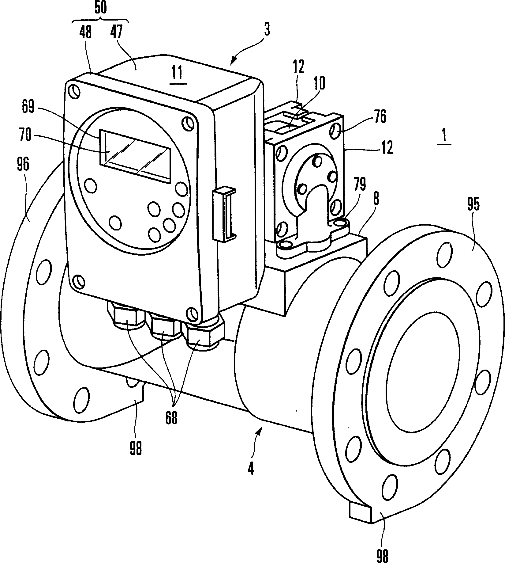
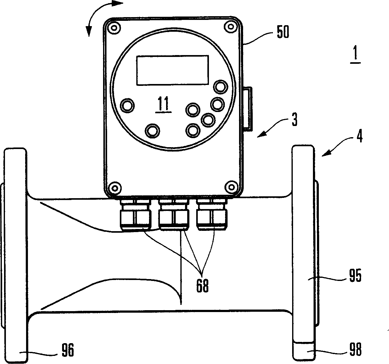
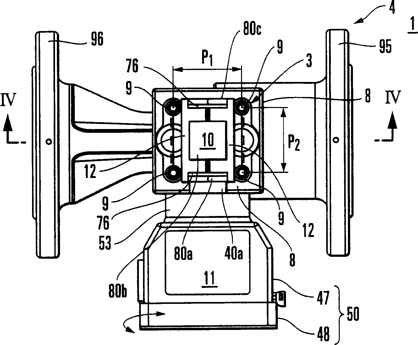
[0029] Figures 1 to 7 Shown is a restrictive flow meter according to a first embodiment of the present invention. In this embodiment, a differential pressure / pressure transmitter is used as a restricted flow meter. This embodiment shows a case where the restrictive flow meter 1 is installed horizontally with respect to horizontally arranged process fluid supply pipes (hereinafter simply referred to as pipes) 2A and 2B. Such as figure 1 As shown, the limiting flow meter 1 is composed of a pipe body 4 formed by a straight pipe, and a differential pressure transmitter 3 installed to the pipe body 4 . Note that the adapter 5 is not used when the restrictor flowmeter 1 is installed horizontally.

[0030] The differential pressure transmitter 3 includes a detection portion 10 fixed to the pipe body 4 , an in-meter transfer portion 11 pivotably connected to the detection portion 10 , and a pair of pressure guide covers 12 covering both side surfaces of the detection portion 10 . ...


PUM


Abstract

A differential pressure / pressure transmitter includes a detecting section, a transmitting section, and a pair of pressure introducing covers. The detecting section has a pair of barrier diaphragms in its opposing side surfaces, and detects a differential pressure of a to-be-measured fluid applied to the pair of barrier diaphragms. The transmitting section is attached to the detecting section. The pressure introducing covers have pressure introducing holes for guiding pressure to the pair of barrier diaphragms, and hold the two side surfaces of the detecting section, thus covering the pair of barrier diaphragms. The detecting section is held by the pair of pressure introducing covers such that its angle is changeable about a center axis thereof. The transmitting section is attached such that its angle can be changed about a center axis thereof which is perpendicular to the center axis of the detecting section.

Description

technical field [0001] The present invention relates to field-mounted differential pressure or pressure indicating transmitters (hereinafter collectively referred to as differential pressure / pressure Transmitters), especially related to differential pressure / pressure transmitters that can freely change the installation angle and direction relative to the process fluid (process fluid) supply pipeline, as well as the reading direction of the indicator (instrument) according to the conditions of the installation site . Background technique [0002] Generally, a differential pressure / pressure transmitter installed on site is composed of a detection part (pressure receiving part) and a transmission part (converting part), the detection part detects the differential pressure of the fluid to be measured acting on a pair of isolation diaphragm plates, The transmission part has a power supply connected to the terminal block and the output monitor indicator, and transmits the differe...

Claims


Application Information

Patent Timeline
Patent Type & Authority Applications(China)
IPC IPC(8): G01F1/38G01F1/44G01L9/00G01L13/00G01L13/02G01L19/00G01L19/08
CPCG01L19/0645G01L19/0023G01F1/383G01F1/44
Inventor 池田勇
Owner YAMATAKE HONEYWELL CO LTD
Learn More