Powder plasma welding device and welding method

A technology of a welding device and a welding method, applied in the directions of plasma welding equipment, plasma, welding equipment, etc., can solve problems such as fusion welding that is not suitable for mutual bonding

Inactive Publication Date: 2004-08-04
PANASONIC CORP
View PDF2 Cites 2 Cited by
  • Summary
  • Abstract
  • Description
  • Claims
  • Application Information

AI Technical Summary

Problems solved by technology

For this reason, the so-called "unsuitable for fusion welding in which the workpieces are fully melted and joined to each other" has arisen.

Method used


Image

  • Powder plasma welding device and welding method
  • Powder plasma welding device and welding method
  • Powder plasma welding device and welding method

Examples


Embodiment Construction

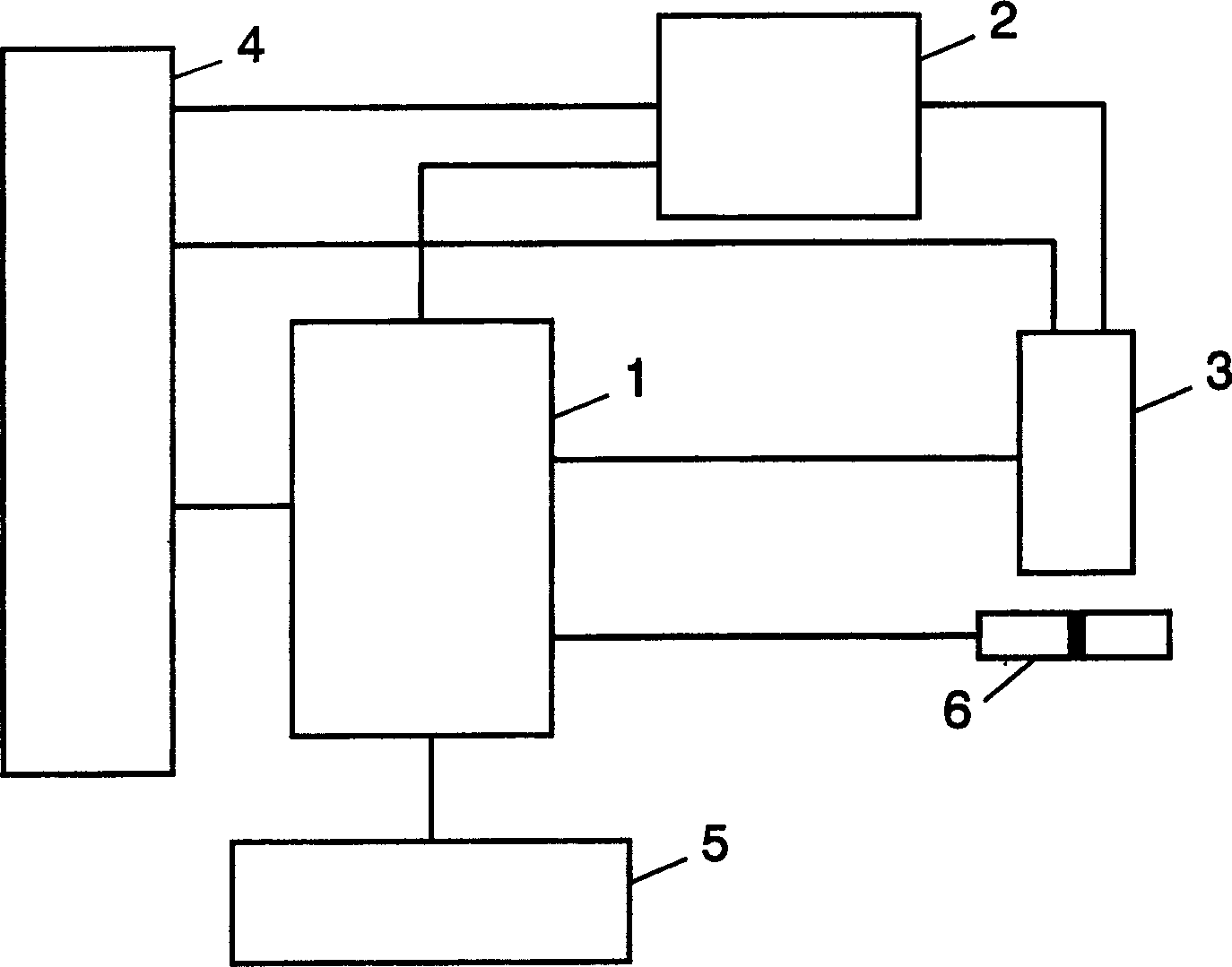
[0014] exist figure 2 Among them, the powder plasma welding device has: a welding torch 3; a power supply 1 that supplies power to the welding torch 3; a feeding device 2 that supplies powder to the welding torch 3; a gas supply device 4 that supplies gas to the welding torch 3 and the feeding device 2; 1 and the feeding device 2 output the control device 5 of the setting signal; the workpiece 6.

[0015] The description of the operation of the welding device with the above structure is as follows. The control device 5 outputs the welding condition setting value of the powder feeding amount and the welding start signal to the power source 1 and the feeding device 2 . The feeding device 2 determines the powder feeding amount level according to the powder feeding amount setting value from the control device 5 . The power supply 1 determines the output power level to the welding torch 3 according to the set value input from the control device 5 . In addition, the power supply...


PUM


Abstract

A plasma powder welding device in this invention comprises a powder having an identical kind of main component as that of a work piece, a feeder feeding the powder to the work piece, a welding torch generating a plasma between itself and the work piece for focusing the powder fed by the feeder on the work piece and transferring the powder to the work piece, and a power source supplying an electric power to the welding torch, wherein a distance from the welding torch to a focal point to which the powder is focused is set nearly equal to or more than the height of the torch.

Description

technical field [0001] The present invention relates to a plasma welding device and a welding method (hereinafter referred to as: powder plasma welding device and powder plasma welding method) using powder as filler metal in welding of metal materials. Background technique [0002] The plasma welding method is a welding method that can improve welding efficiency compared with the TIG welding method due to its high arc energy density, and the welding quality is not inferior to the TIG welding method. The powder plasma welding method using powder as a filler metal in this plasma welding method has been widely used in recent years as a surfacing welding method for improving the surface of a workpiece. [0003] Conventionally, the powder used in this powder plasma welding method has a composition different from that of the workpiece in order to improve wear resistance (see, for example, JP-A-11-277246 (pp. 2-4, FIG. 1 )). [0004] Also, set a long torch height and make the foca...

Claims


Application Information

Patent Timeline
Patent Type & Authority Applications(China)
IPC IPC(8): B23K9/32B23K10/02H05H1/42
CPCH05H1/42B23K10/02B23K9/324
Inventor 印南哲木曾博之井原英树
Owner PANASONIC CORP
Why Eureka
Try Eureka