
Fuel jetter of engine

A technology of fuel injection device and engine, which is applied in the directions of fuel injection device, low pressure fuel injection, low pressure fuel injection, etc., to achieve the effect of avoiding processing procedures and the number of parts, and easy disposal of volatile gas

Inactive Publication Date: 2004-09-22
HONDA MOTOR CO LTD
View PDF0 Cites 0 Cited by
  • Summary
  • Abstract
  • Description
  • Claims
  • Application Information

AI Technical Summary

Problems solved by technology

Moreover, in the remaining air discharged from the safety valv

Method used


Image

  • Fuel jetter of engine
  • Fuel jetter of engine
  • Fuel jetter of engine

Examples


Embodiment Construction

[0022] Hereinafter, an embodiment of the present invention will be described based on an example of the present invention shown in the drawings.

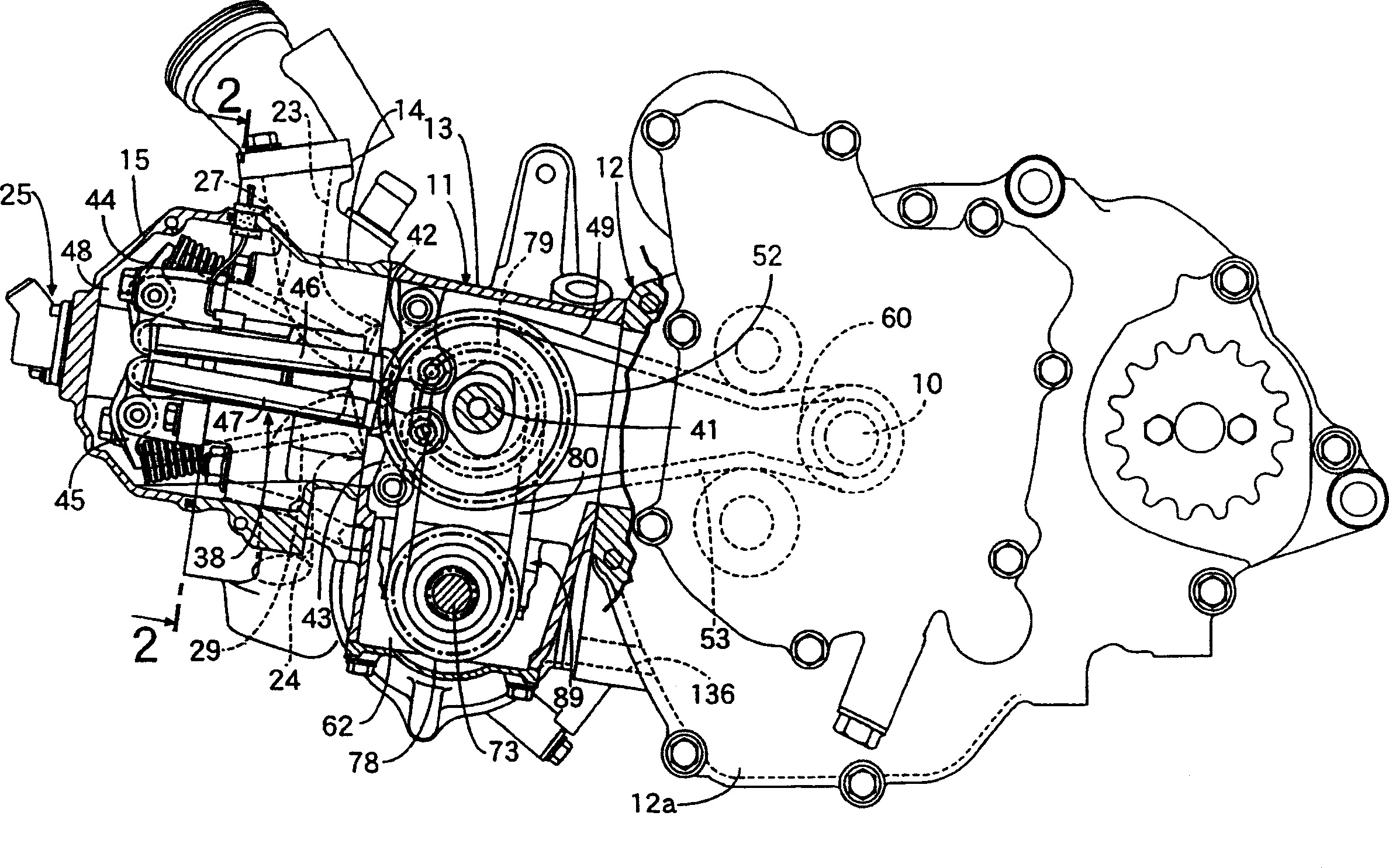
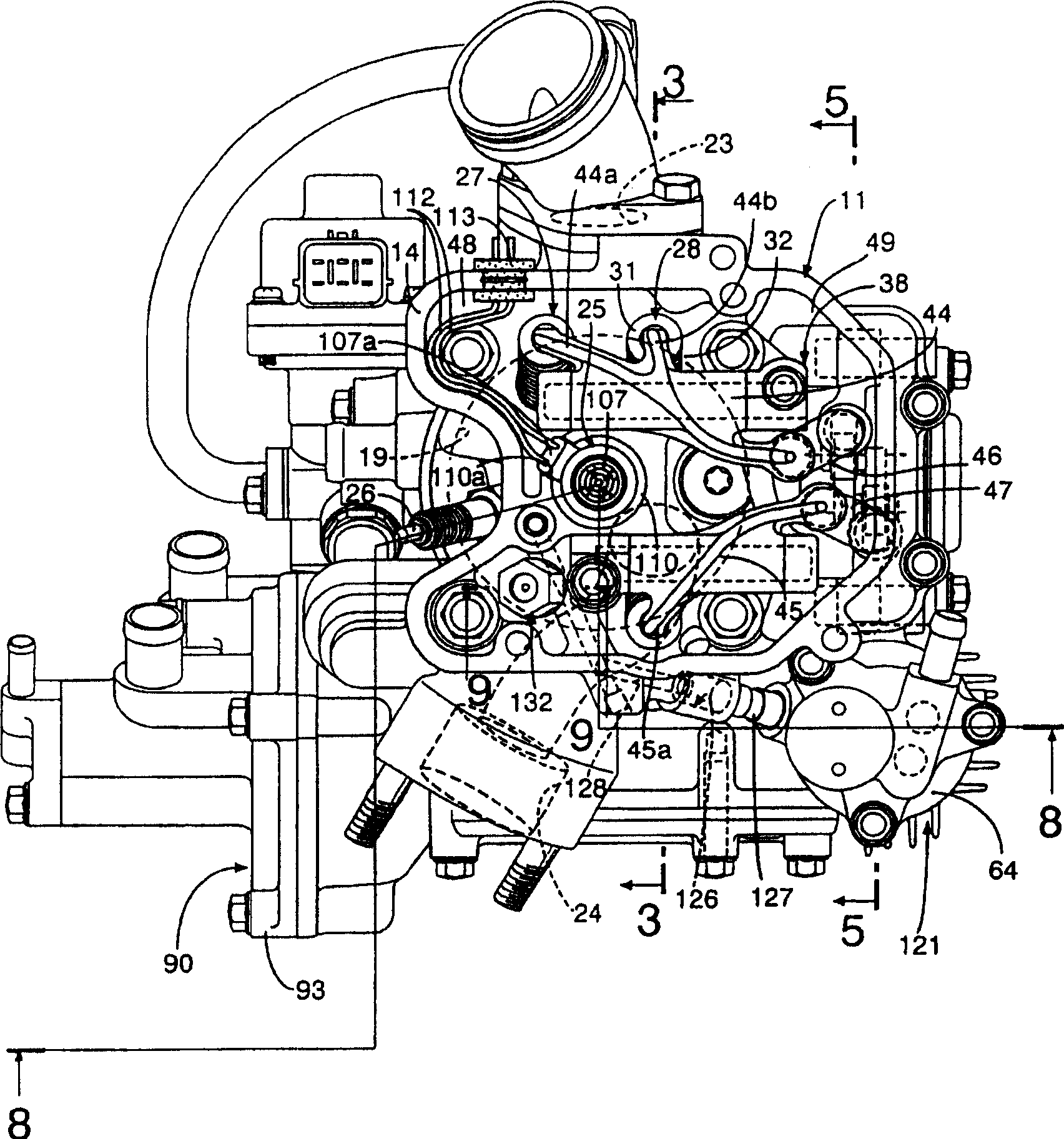
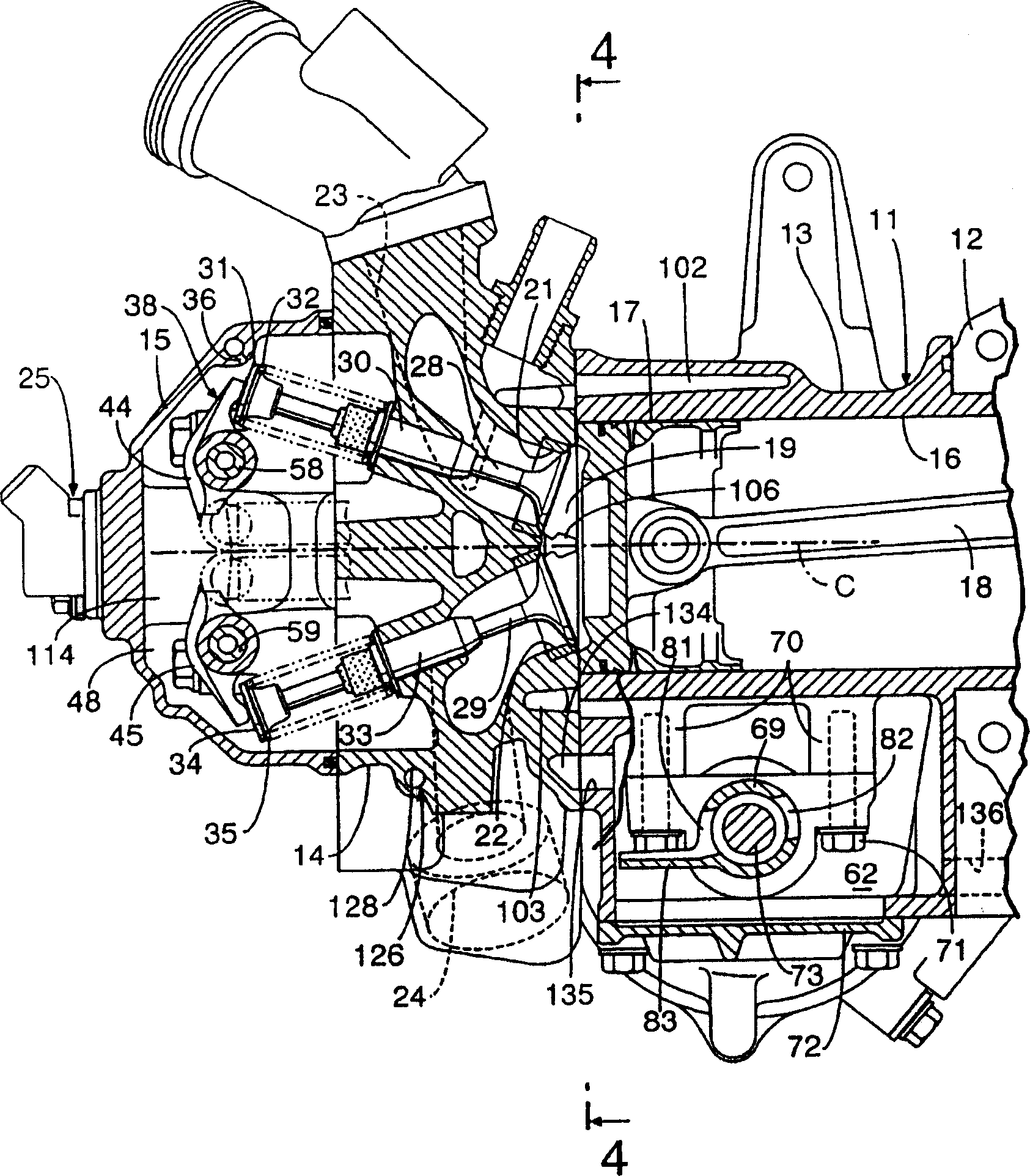
[0023] Figures 1 to 9 An embodiment of the present invention is shown, figure 1 is a partial longitudinal sectional side view of the engine, figure 2 with the cover removed figure 1 The 2-2 line view, image 3 yes figure 2 3-3 line cutaway view of the, Figure 4 yes image 3 4-4 line sectional view of the, Figure 5 yes figure 2 The 5-5 line sectional view, Figure 6 yes Figure 5 The 6-6 line sectional view, Figure 7 yes Figure 5 The 7-7 line sectional view of Figure 8 is along the figure 2 A longitudinal sectional side view of the engine of the 8-8 line, Figure 9 yes figure 2 Line 9-9 enlarged sectional view.

[0024] First refer to figure 1 The engine body 11 of the overhead valve four-stroke water-cooled single-cylinder engine comprises: a crankcase 12, a cylinder block 13 combined with the crankcase 12,...


PUM


Abstract

To extremely facilitate evaporation treatment of lubricating oil and intermixed fuel components that may be included in excess air discharged from a relief valve, in a fuel injection device for an engine equipped with an injector for directly injecting fuel into a combustion chamber together with compressed air, a compressed air supply source for supplying the compressed air to the injector and the relief valve interposed on the way of a compressed air supplying passage joining the compressed air supply source to the injector. The excess air discharged from the relief valve 132 is introduced to a lubricated part housing chamber 48 formed inside an engine main body 11 so as to face to a lubricated part. (C)2004,JPO&NCIPI .

Description

technical field [0001] The present invention relates to a fuel injection device for an engine, which comprises: an injector for directly injecting compressed air and fuel into a combustion chamber, a compressed air supply source for supplying compressed air to the injector, and a device connected to the compressed air supply source and The compressed air of the injector is supplied to the safety valve in the way. Background technique [0002] For example, Patent Document 1 and the like disclose a fuel injection device that discharges the remainder of the compressed air supplied to the injector by an air pump through a safety valve. [0003] Patent Document 1: Patent No. 3159998. [0004] In the conventional fuel injection device described above, the residual air discharged from the safety valve is introduced into the exhaust pipe that guides the exhaust gas from the engine. In the compressed air supplied to the injector, there may be lubricating oil used by the air pump. ...

Claims


Application Information

Patent Timeline
IPC IPC(8): F02M69/00F02F1/24F02F1/42F02M61/14F02M61/18F02M69/08
CPCY02T10/123Y02T10/12
Inventor 塙薰
Owner HONDA MOTOR CO LTD
Learn More