Z shaped separator used for separating product flow

A product flow and separator technology, applied in the application and manufacture of cigars, tobacco, etc., can solve the problems of unstable supply, difficult separation device, difficult to obtain satisfactory separation results, etc., and achieve the effect of uniform and continuous feeding

Active Publication Date: 2004-10-06
柯尔柏技术有限责任公司
View PDF0 Cites 0 Cited by
  • Summary
  • Abstract
  • Description
  • Claims
  • Application Information

AI Technical Summary

Problems solved by technology

Thus, on the one hand, it is difficult to achieve an orderly and continuous supply to and into the separation device
On the other hand, this unstable supply of product streams makes it difficult to obtain satisfactory separation results

Method used


Image

  • Z shaped separator used for separating product flow
  • Z shaped separator used for separating product flow
  • Z shaped separator used for separating product flow

Examples


Embodiment Construction

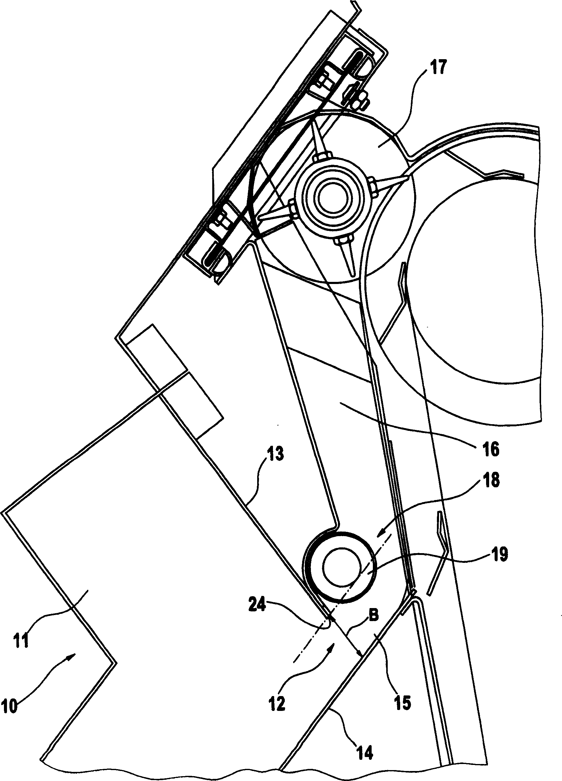
[0020] The zigzag separator shown in the figure is used to separate a product stream, preferably a product stream substantially consisting of tobacco components, in a distributor device for feeding a cigarette plying machine.

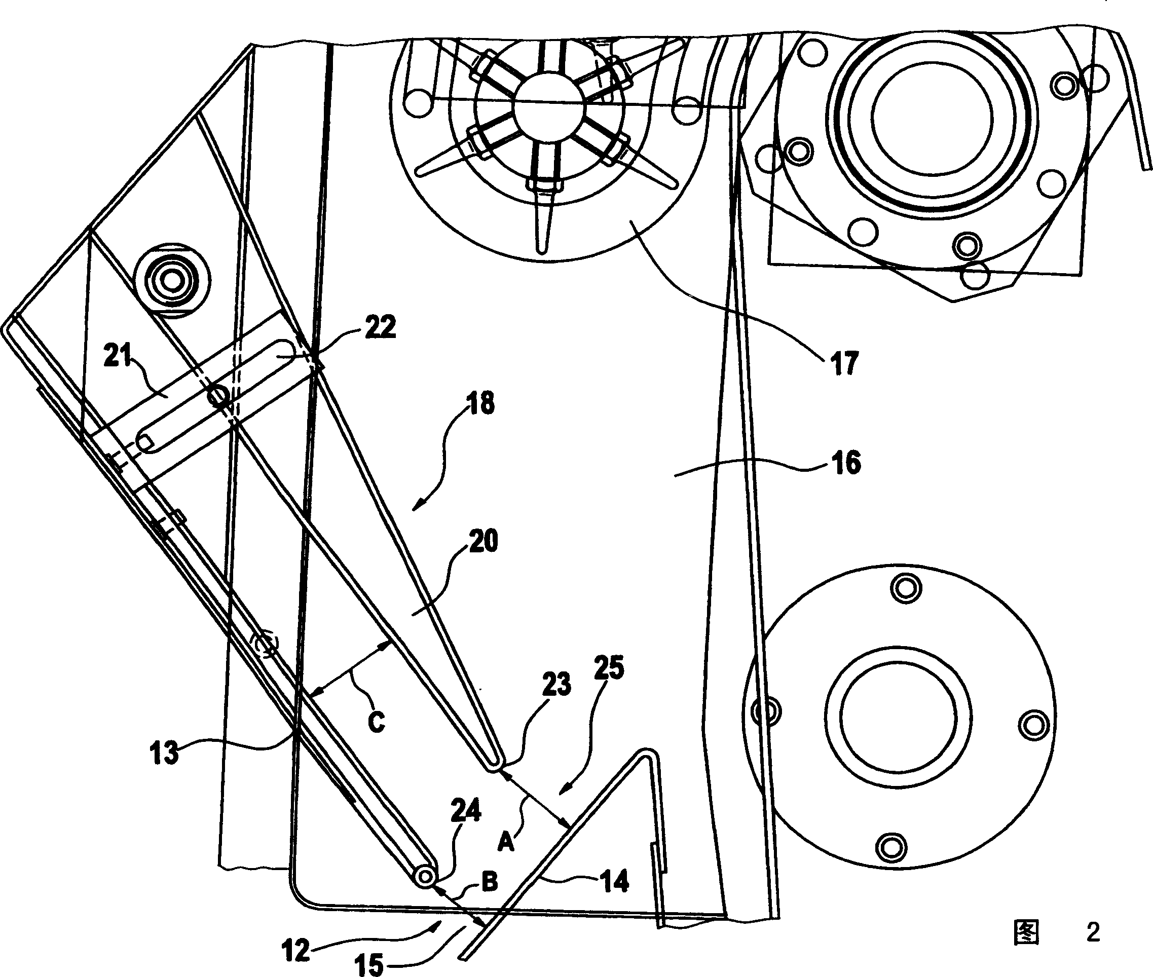
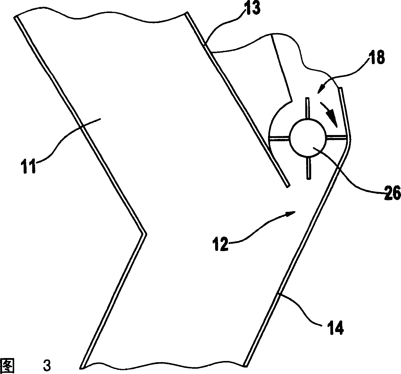
[0021] in accordance with figure 1 The separating device 10 of the exemplary embodiment shown is designed as a so-called zigzag separator 11 and is part of a distributor device which is only partially shown. The zigzag separator 11 is arranged approximately vertically within the distributor device. The zigzag separator 11 has an inlet 12 for feeding the product flow. Alternatively, multiple inlets are also conceivable. The inlet 12 is formed by side walls, namely an upper side wall 13 and a lower side wall 14 , which in turn form an opening 15 . To this end, the upper side wall 13 stands approximately perpendicularly on the lower side wall 14 at a distance B, so that the product flow is guided into the zigzag separator 11 .

[0022] A feed channel 1...


PUM


Abstract

Separating device (10) for separating a product flow, especially for separating parts of a product flow that are to be processed or not to be processed within a distribution device for loading a cigarette-making machine, comprises a vertical zigzag separator (11) and at least one inlet (12) for the product flow to be separated. An insertion aid (18) for the product flow is arranged in the zigzag separator in the region of the inlet. An Independent claim is also included for a process for separating a product flow. Preferred Features: The insertion aid is a rotating roller (19). The inlet is formed by two side walls (13, 14) of the zigzag separator. The roller is arranged in the region of a free end (24) of the upper side wall.

Description

technical field [0001] The invention relates to a separation device for separating a product flow, in particular for separating a part of the product flow to be treated and an untreated part of the product flow in a distributor device for feeding a cigarette plying machine , the separation device is configured as a substantially vertically aligned zigzag (or zigzag) separator and has at least one inlet for the product stream to be separated. [0002] The invention also relates to a method for separating a product stream, in particular for separating the part of the product stream to be treated and the untreated part of the product stream in a distributor device for feeding a cigarette plying machine. Partly, the method comprises the steps of: introducing the product stream into a separation device, separating the product stream in the separation device, and discharging the separated product stream from the separation device. Background technique [0003] During the producti...

Claims


Application Information

Patent Timeline
IPC IPC(8): A24C1/02A24C5/00A24C5/39
Inventor R·林德曼P·舒马赫尔
Owner 柯尔柏技术有限责任公司
Why Eureka
Try Eureka