Evaporator for separated heat tube

A separate heat pipe and evaporator technology, applied in the direction of evaporation, separation methods, chemical instruments and methods, etc., can solve the problems of heat source and evaporator thermal resistance increase, evaporator heat transfer capacity limitation, heat transfer deterioration, etc., to achieve Reduce the superheat of the wall surface, improve the characteristics of variable working conditions, and save the amount of consumption

Inactive Publication Date: 2004-10-13
中科热科技江苏有限公司
View PDF0 Cites 21 Cited by
  • Summary
  • Abstract
  • Description
  • Claims
  • Application Information

AI Technical Summary

Problems solved by technology

If the heat source is on a certain surface, the heat source heats the evaporator through a solid wall of the evaporator by heat conduction. Since only one surface of the evaporator is coupled with the heat source, the contact surface area is usually constant, so it is difficult to increase the evaporation heat transfer area. To improve the heat transfer capacity, the heat transfer capacity of the evaporator is greatly limited; in addition, if the pressure inside the evaporator is high, the heating surface of this evaporator is prone to deformation and warping during operation, which makes the heat source and The thermal resistance between the evaporators increases and the heat transfer deteriorates

Method used


Image

  • Evaporator for separated heat tube
  • Evaporator for separated heat tube
  • Evaporator for separated heat tube

Examples


Embodiment Construction

[0025] The present invention will be described in further detail below with reference to the accompanying drawings and specific embodiments.

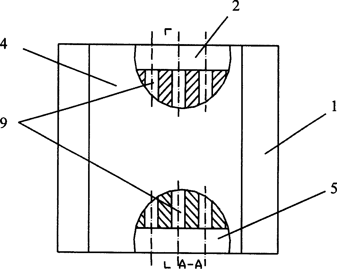
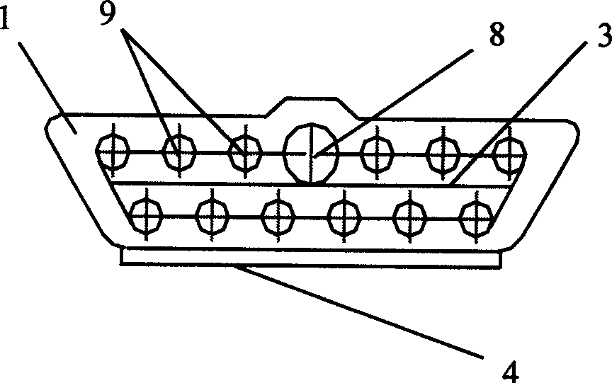
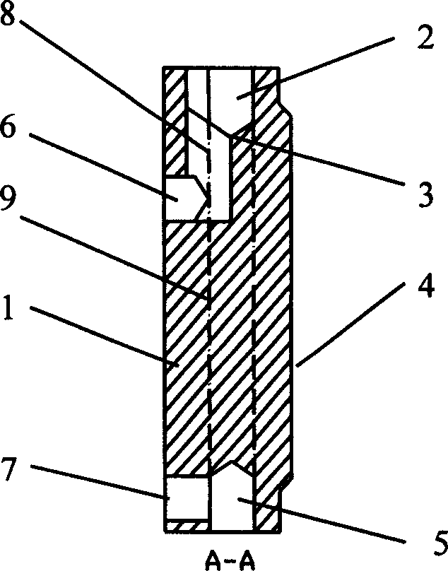
[0026] like figure 1 The shown evaporator is a metal plate 1 as a whole, and its front surface is a heating surface 4, which is in use against the solid wall of the heat source to absorb heat by conduction. A plurality of vertical parallel straight channels 9 are opened in the metal plate 1, and a liquid working medium is contained therein. In this way, when the heating surface 4 absorbs heat, the heat is rapidly conducted to various positions of the metal plate 1, so that the liquid working medium in the straight channel 9 absorbs heat and evaporates. Therefore, the evaporative heat exchange area of ​​the evaporator can be expanded by the evaporating surface of one coupling heating surface 4 of the metal plate to the sum of the column areas of all channels 9 . Generally speaking, the evaporation heat exchange area of ​​the evaporator...


PUM


Abstract

The present invention discloses an evaporator for separated heat pipe. It includes parallel-connected channels and metal plate. Said parallel-connected channels are integrally formed in the interiour of metal plate along the vertical direction. The top portion of the metal plate is equipped with a steam header formed into a hollow cavity communicated with upper end hole of the described channel, on the top cover of the steam header a steam outlet is set. The metal plate also includes a reflux system including recycle tube and liquid header formed into hollow cavity, the liquid header is communicated with exteriour of metal plate by means of recycle tube, and said liquid header is communicated with the described channel. Said invention also provides a reflux system correspondent to falling-film evaporation, the liquid header is positioned in the lower portion of upper end hole of the channel and close to upper end hole of the channel, and the upper end hole of liquid header is communiated with upper end hole of channel by means of steam header.

Description

technical field [0001] The present invention relates to an evaporator, and more particularly, the present invention relates to an evaporator for a split heat pipe. Background technique [0002] At present, there are only two types of evaporator structures for separate heat pipes: [0003] (1) Parallel metal tube (with or without fins) evaporator. The parallel metal pipes are connected in parallel between the upper and lower headers to form an evaporator, see literature [1]: V.Dube, Effect of Non Condensable Gases on The Performance of Loop Thermosyphon Heat Exchangers, D6, 12 th Int.Heat Pipe Conference, Moscow, May 19-24, 2002, Preprint Vol.2; Literature [2]: Zhuang Jun, Zhang Hong, Heat Pipe Technology and Its Engineering Application, Chemical Industry Press, 2000.6, 189-190; Literature [3]: Jin Mingcong, Chen Yuanguo, Heat Pipe and Heat Pipe Heat Exchanger, Chongqing University Press, 1986.8, 179-185. This structure is only suitable for the case where the heat source ...

Claims


Application Information

Patent Timeline
Patent Type & Authority Applications(China)
IPC IPC(8): B01D1/00
Inventor 曲伟
Owner 中科热科技江苏有限公司
Why Eureka
Try Eureka