Heat pipe device

A heat pipe device and pipe body technology, applied in the field of thermal control equipment, can solve the problems of high flexibility of heat pipe device heat transfer, large heat transfer area can not be taken into account, to achieve compact structure, long-distance heat transfer, and extended evaporation heat transfer area effect

Pending Publication Date: 2018-07-13
TECHNICAL INST OF PHYSICS & CHEMISTRY - CHINESE ACAD OF SCI
View PDF6 Cites 2 Cited by
  • Summary
  • Abstract
  • Description
  • Claims
  • Application Information

AI Technical Summary

Problems solved by technology

[0006] The purpose of the present invention is to provide a heat pipe device with an expandable heat exchange area to solve the technical problem that the existing heat pipe device cannot take into account the high flexibility of heat transfer and the large heat exchange area

Method used


Image

  • Heat pipe device
  • Heat pipe device
  • Heat pipe device

Examples


Embodiment 1

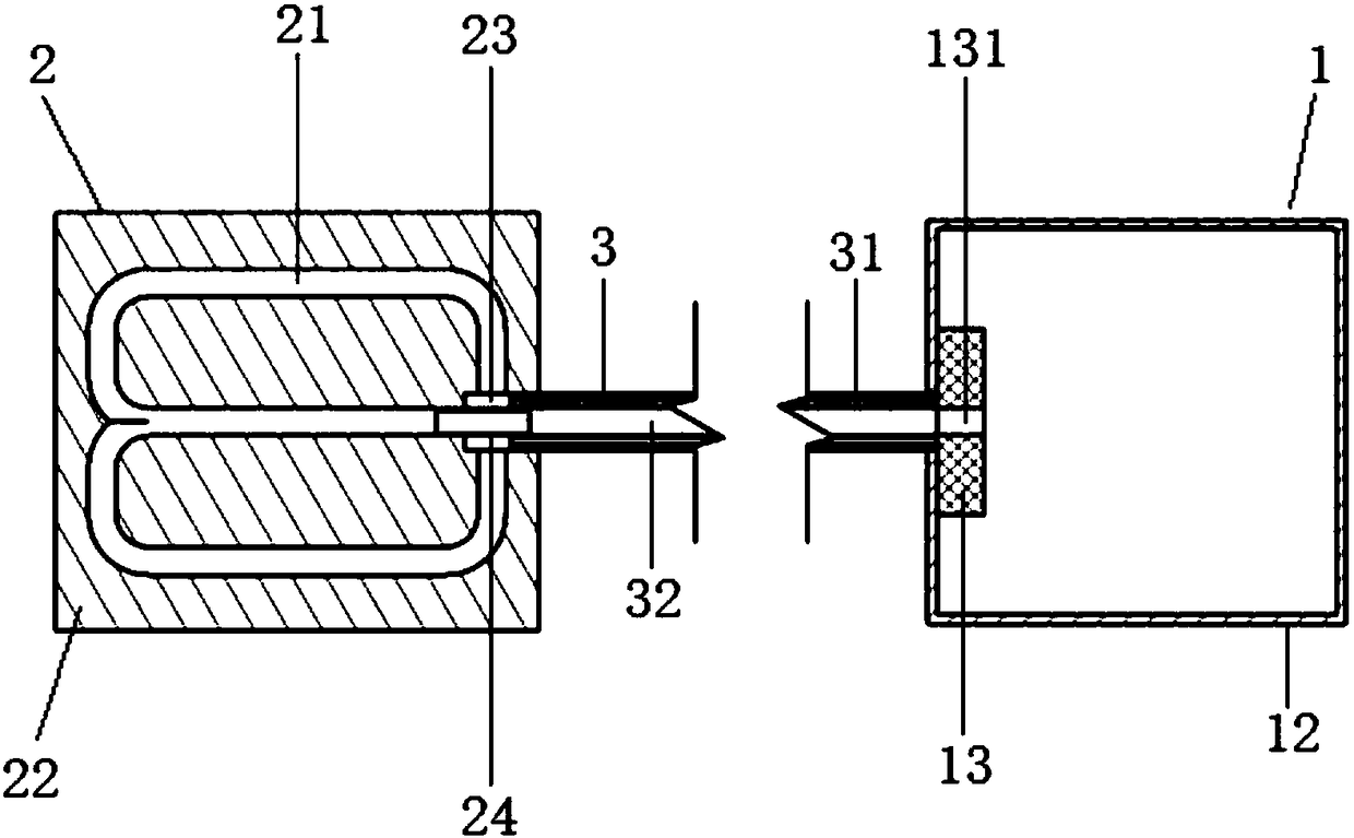
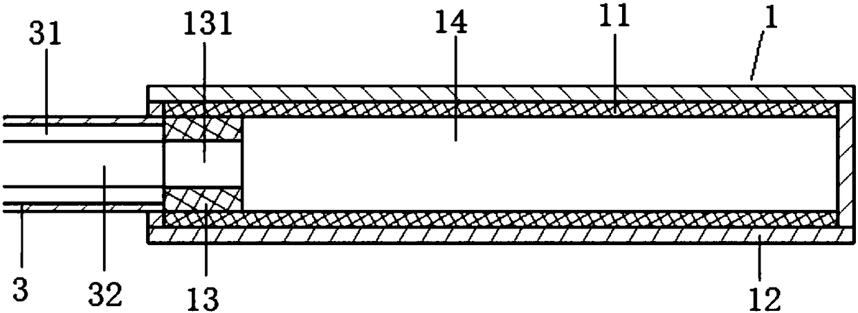
[0037] Such as Figure 1 ~ Figure 3 As shown, this embodiment provides a heat pipe device, including a condenser 2 , a transfer pipe and an evaporator 1 . The condenser 2, the transfer pipe and the evaporator 1 jointly form a closed chamber, which is filled with a working medium (ie, working fluid), and the condenser 2, the transfer pipe and the evaporator 1 are connected in sequence to form a working medium circuit. In the direction perpendicular to the length of the heat pipe device, the evaporator 1 has at least one cross-sectional dimension larger than the cross-sectional dimension of the transfer pipe. Compared with the internal section of the transfer tube, the interior has a larger evaporation heat exchange area.

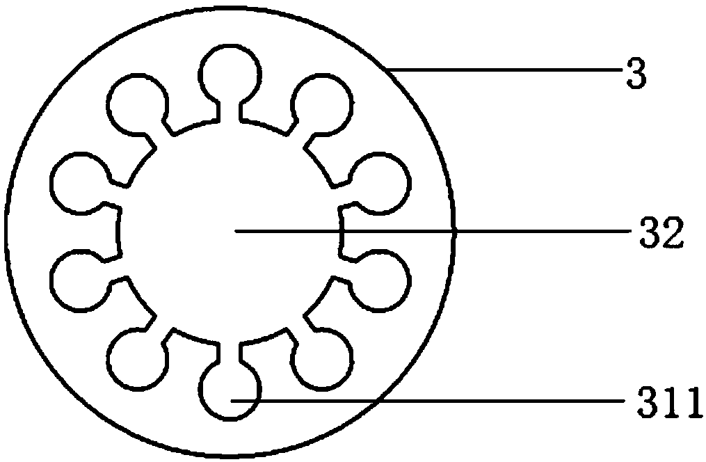
[0038] The transfer tube specifically includes a tube body 3 , a cavity 32 inside the tube body 3 , and a first capillary structure 31 on the inner wall of the tube body 3 . A first end of the cavity 32 communicates with the air inlet of the condenser 2 , a...

Embodiment 2

[0050] In order to make the heat pipe device have a more excellent flexible heat transfer effect, all or part of the pipe body 3 can also be designed as a flexible pipeline, which can be a non-metallic pipe or a metal pipe, such as a plastic pipe, rubber pipe, stainless steel pipe, etc. Thin-walled tubes, copper tubes, etc., or corrugated tubes, metal hoses, etc., or a combination of at least two of the above structures. By arranging flexible pipelines, the heat pipe device can be made more flexible, not only capable of bending, torsion, and even reciprocating swing, to meet the heat dissipation requirements of relative motion between the cold source and the heat source.

[0051] Such as Figure 5 ~ Figure 7 As shown, this embodiment also provides a heat pipe device, which is basically the same as the heat pipe device in Embodiment 1, and the similarities will not be repeated. The difference is that the first capillary structure 31 of this embodiment is the same as that of Emb...

Embodiment 3

[0056] This embodiment provides another heat pipe device, the structure of which is basically the same as that of Embodiment 1 or Embodiment 2, and the similarities will not be repeated. The difference lies in: Figure 4 As shown, the heat pipe device of this embodiment defaults to the condensation pipeline 21, but a section of the left end of the pipe body 3 is coupled with the plate body 22, that is, the pipe body 3 of the transfer pipe directly extends into the condenser 2, and the pipe body 3 The part extending into the condenser 2 replaces the condensing pipeline 21, so that the gaseous working medium is condensed into a liquid at a certain length of the condensation section at the end of the tube body 3, and gathers in the condensation section, and then passes through the first capillary structure in the tube body 3 31 flows into evaporator 1. In this embodiment, the length of the condensation section of the tube body 3 can be designed according to the size of the heat e...


PUM


Abstract

The invention relates to heat control equipment, in particular to a heat pipe device. The heat pipe device comprises a condenser, a conveying pipe and an evaporator, wherein the condenser, the conveying pipe and the evaporator are connected in sequence to form a closed cavity; and in the length direction perpendicular to the heat pipe device, at least one cross section of the evaporator is largerthan the cross section size of the conveying pipe. The heat pipe device is simple in appearance, compact in structure and easy to bend, and is convenient for flexible layout of the system, and has more excellent flexible heat transfer and long-distance heat transfer effects; in the length direction perpendicular to the heat pipe device, at least one cross section of the evaporator is larger than the section size of the conveying pipe, so that the evaporation heat exchange area of the heat pipe device is greatly expanded, and therefore, flexible heat transfer can be carried out; and a large heat exchange area is achieved, and the device conveniently couples and assembles a radiator with a larger area, and has a better heat dissipation effect.

Description

technical field [0001] The invention relates to a heat control device, in particular to a heat pipe device. Background technique [0002] A heat pipe is a highly efficient heat transfer device, its heat transfer capacity is one or two orders of magnitude higher than that of metal, and it is called a thermal superconductor. The traditional heat pipe mainly includes a metal shell, capillary structure and working medium. The capillary structure is usually composed of channels or sintered porous structures, and is distributed in the entire length direction of the heat pipe. Simple, stable heat transfer performance, widely used in aviation, aerospace, communication, electronic devices and other fields. [0003] At the same time, this structure also has some adverse effects. First, when the heat pipe needs to conduct long-distance heat transfer, it is required to have a large capillary force and small flow resistance. When reducing the capillary size of the capillary structure i...

Claims


Application Information

Patent Timeline
Patent Type & Authority Applications(China)
IPC IPC(8): F28D15/02F28D15/04
CPCF28D15/0233F28D15/0266F28D15/046
Inventor 赵雅楠梁惊涛
Owner TECHNICAL INST OF PHYSICS & CHEMISTRY - CHINESE ACAD OF SCI
Why Eureka
Try Eureka