Output correction method of image forming device and image forming appts.

An image reading device and image technology, applied in printing devices, image communication, printing and other directions, can solve the problems of difficult correction, density dispersion, and large position, so as to reduce density unevenness, improve correction accuracy, reduce Determining the effect of discrete

Inactive Publication Date: 2004-10-27
KONICA MINOLTA OPTO
View PDF3 Cites 11 Cited by
  • Summary
  • Abstract
  • Description
  • Claims
  • Application Information

AI Technical Summary

Problems solved by technology

[0010] In addition, if a wide correction image is output to correct the recording element, it takes a long time to measure the density of the image. Therefore, if the stability of the density measurement is not sufficient, there will be dispersion in the

Method used


Image

  • Output correction method of image forming device and image forming appts.
  • Output correction method of image forming device and image forming appts.
  • Output correction method of image forming device and image forming appts.

Examples


Embodiment 1

[0252] Hereinafter, Embodiment 1 of the present invention will be described in detail with reference to the drawings. However, the scope of the invention is not limited by the illustrated examples.

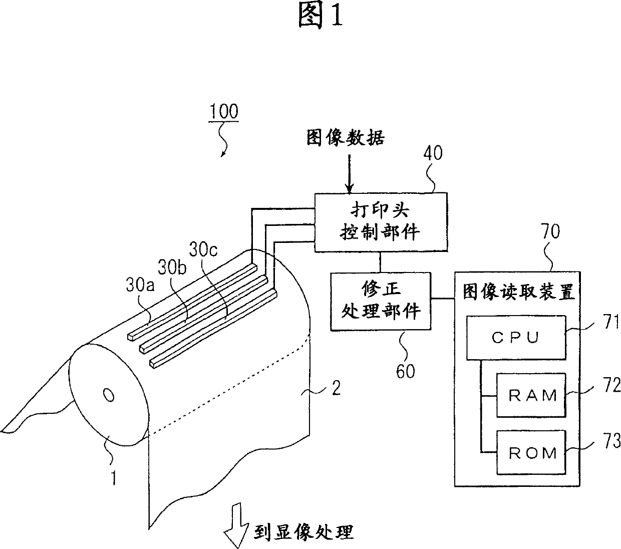
[0253] FIG. 1 shows a schematic configuration diagram of an image forming apparatus 100 in this embodiment.

[0254] As shown in FIG. 1, the image forming apparatus 100 includes a support drum 1, a red print head 30a, a green print head 30b, a blue print head 30c, a print head control unit 40, a correction processing unit 60, an image reading device 70, and the like. is constituted. In this embodiment, photosensitive paper for color photography (hereinafter referred to as photosensitive paper) that is a silver halide photosensitive material is used as a recording material.

[0255] The support drum 1 is a conveyor that is rotated by an unillustrated drive source. The support drum 1 conveys the photosensitive paper 2 conveyed from a roller (not shown) in the direction of the arr...

Embodiment 2

[0428] Next, Embodiment 2 of the present invention will be described in detail with reference to the drawings. The image forming apparatus 300 related to the second embodiment differs from the first embodiment in the light flux correction processing method of the recording element performed by the image forming apparatus 300 and the recording material used. Therefore, when describing the second embodiment, the same configurations as those of the above-mentioned first embodiment are given the same reference numerals, and description thereof will be omitted.

[0429] The image forming apparatus 300 includes a support drum 1, a red printhead 30a, a green printhead 30b, a blue printhead 30c, a printhead control unit 40, a correction processing unit 60, an image reading device 80, and the like. In this embodiment, as a recording material, color photographic photosensitive paper (hereinafter referred to as photosensitive paper) 22 which is a silver halide photosensitive material is ...

Deformed example 1

[0498] For example, one correction image can be generated, one image can be set twice in different directions, and read in two times. In FIG. 30 , one graph 33A is installed in the image reading device twice, and a modification 1 is given as a reading method.

[0499] Fig. 30(a) is the installation direction for the first time, and (b) is the installation direction for the second time.

[0500] As shown in (a), first, the arrangement direction of the corrected image included in the graph 33A is arranged so as to be the first direction in the forward direction of the arrangement direction of the recording elements, read in this state, and obtain the first read. fetch information.

[0501] Next, as shown in (b), first, the alignment direction of the corrected image in the graph 33A is arranged so that it becomes the opposite direction to the alignment direction of the recording elements, that is, as the second direction opposite to the first direction, and the second reading is...


PUM


Abstract

Provided is a means of precisely reducing irregular concentrations in an array-like printhead for a long picture. An information of concentrations from each image N to be corrected (step S2) is obtained in the first place before a concentration information data DNi that corresponds to each recording pixel i is specified(step S4), and a deviation -DNi=DNi-DNave, iscalculated treating an average of the concentration data DNi as DNave (step S5). Then, a difference of the quantity of light, -ENi, corresponding to the deviation -ENi is obtained using a straight line of conversion (step S6), followed by (step S7) that calculates a correction quantity CNi=10(--ENi) that meets each recording pixel and (step S9) that composes the quantity of correction CNi calculated from each correction image N.

Description

technical field [0001] The present invention relates to an output correction method and an image forming apparatus for an image forming apparatus that corrects variations in recording characteristics of recording elements of a print head that arranges recording elements in an array and records an image. Background technique [0002] In recent years, due to the popularization of digital cameras, there are high expectations for improvement in the printing capability, image quality, and other performance of digital small laboratory machines as image forming devices. In particular, the demand for printing using large paper is increasing, and an exposure device suitable for a print head for which a plurality of recording elements are arranged in an array is being developed. [0003] In general, light-emitting recording elements constituting an array printhead have a dispersion of about 20% to 40% in each light-emitting characteristic. If the correction of the variation is insuff...

Claims


Application Information

Patent Timeline
IPC IPC(8): B41J29/46B41J2/44B41J2/45B41J2/455H04N1/23
Inventor 中花田学服部毅佐藤武治和田谦一松原范明
Owner KONICA MINOLTA OPTO
Why Eureka
Try Eureka