
Power source and LCD device and drive method thereof

A liquid crystal display and power supply technology, which can be used in static indicators, cathode ray tube indicators, televisions, etc., and can solve problems such as abnormal lighting

Inactive Publication Date: 2004-10-27
SAMSUNG DISPLAY CO LTD
View PDF1 Cites 6 Cited by
  • Summary
  • Abstract
  • Description
  • Claims
  • Application Information

AI Technical Summary

Problems solved by technology

The object of the present invention is to provide a kind of power supply, a kind of liquid crystal display and its driving method, wherein can make the moiré fringe that produces on the liquid crystal display screen when changing between dynamic image mode and static image mode, and lamp does not emit light. Normal problems can also be solved

Method used


Image

  • Power source and LCD device and drive method thereof
  • Power source and LCD device and drive method thereof
  • Power source and LCD device and drive method thereof

Examples


Embodiment Construction

[0026] Preferred embodiments of the present invention will be described in detail below with reference to the accompanying drawings.

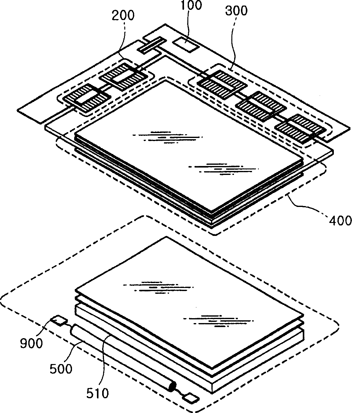
[0027] figure 1 is a view showing a liquid crystal display according to an embodiment of the present invention.

[0028] refer to figure 1 , the liquid crystal display according to the embodiment of the present invention comprises: a liquid crystal assembly, and this assembly comprises: a liquid crystal panel 400 injecting liquid crystal between the double-layer glasses; a driving circuit 200, 300 for driving the liquid crystal panel 400; a timing The controller 100 is used to generate control signals to control the driving circuits 200, 300; a backlight source including a lamp 500; a reflector 510; a lamp driving unit 900 (ie, a power supply device) for applying high voltage to the lamp 500 voltage to drive the lamp 500.

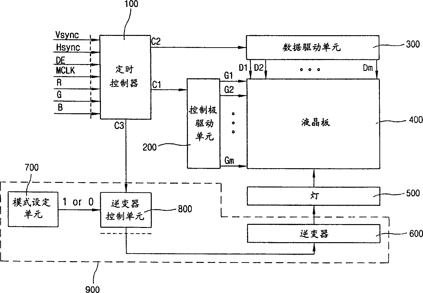
[0029] figure 2 is a block diagram of a liquid crystal display according to an embodiment of the present invention; ...


PUM


Abstract

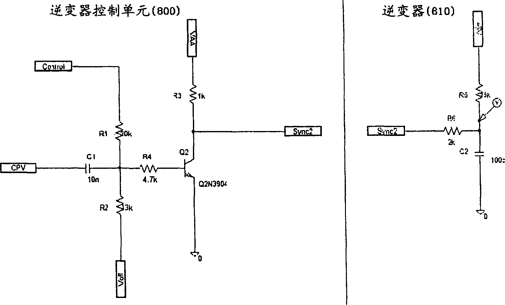
The liquid crystal display device of the present invention comprises a timing controller, a gate driving unit, a data driving unit, a liquid crystal panel, a lamp, an inverter, a mode setting unit, and an inverter control unit. The mode setting unit discriminates a moving-image mode and a still-image mode and provides a specific control signal to the inverter control unit in accordance with the discriminated mode. The inverter control unit operates the inverter in either synchronous mode or asynchronous mode by applying or withholding a timing signal to the inverter, in response to the control signal from the mode setting unit. Preferably, the timing signal is a gate select signal CPV that becomes a horizontal synchronous signal. According to the present invention, a moire phenomenon in still-image mode can be eliminated by driving the lamp in synchronization with the horizontal synchronous signal and the problem of lighting malfunction of the lamp in the moving-image mode can also be eliminated by driving the lamp at the frequency of the inverter itself.

Description

[0001] This application claims priority to Korean Patent Application No. 10-2003-0025239 filed with the Korean Intellectual Property Office on April 21, 2003, the disclosure of which is incorporated herein by reference. technical field [0002] The invention relates to a power supply, a liquid crystal display and a driving method thereof. Background technique [0003] Generally, a liquid crystal display includes a liquid crystal component, and the liquid crystal component includes a liquid crystal display panel, a data drive unit, a control electrode drive unit, and a backlight. [0004] Since the liquid crystal display panel itself of the liquid crystal display cannot emit light, it cannot be used in a place without light, so it is necessary to use a lamp as a backlight for emitting uniform light throughout the entire liquid crystal display panel from its back. [0005] Recently, a liquid crystal display is widely used as a combination of a television and a monitor in which...

Claims


Application Information

Patent Timeline
IPC IPC(8): G02F1/133G09G3/20G09G3/34G09G3/36G09G5/00H04N5/66
CPCG09G2320/062G09G2320/02G09G3/3406G09G2320/0261G02F1/133
Inventor 罗东均
Owner SAMSUNG DISPLAY CO LTD
Learn More