Desinfection chamber unit

A technology of aseptic rooms and curtains, applied in treatment rooms, medical science, hospital equipment, etc., can solve problems such as difficulties in moving in and out, inability of patients to touch and manipulate medical manipulators, and blocking of sight of patients' feet. To achieve the effect of enhancing reliability

Inactive Publication Date: 2004-11-03
SANKI ENG CO LTD
View PDF0 Cites 8 Cited by
  • Summary
  • Abstract
  • Description
  • Claims
  • Application Information

AI Technical Summary

Problems solved by technology

[0013] v) Since the patient's head side is blocked by the box-shaped chamber b, the patient cannot reach and manipulate the medical manipulator on the wall of the ward
[0014] vi) Posts mounted vertically and oppositely on the patient's foot side make moving the bed i into and out of the sterile room h difficult and block the view of the patient's foot side

Method used


Image

  • Desinfection chamber unit
  • Desinfection chamber unit
  • Desinfection chamber unit

Examples


Embodiment Construction

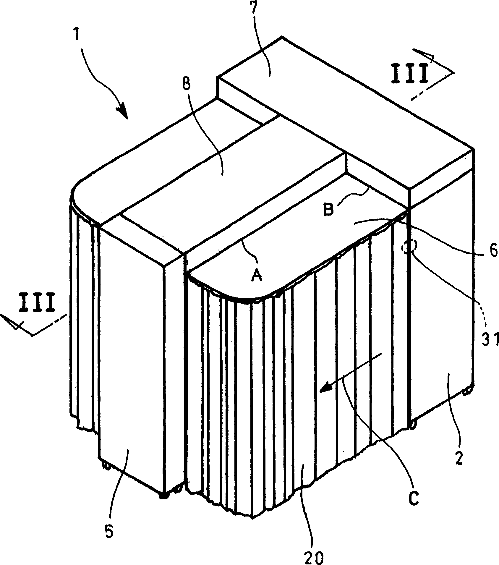
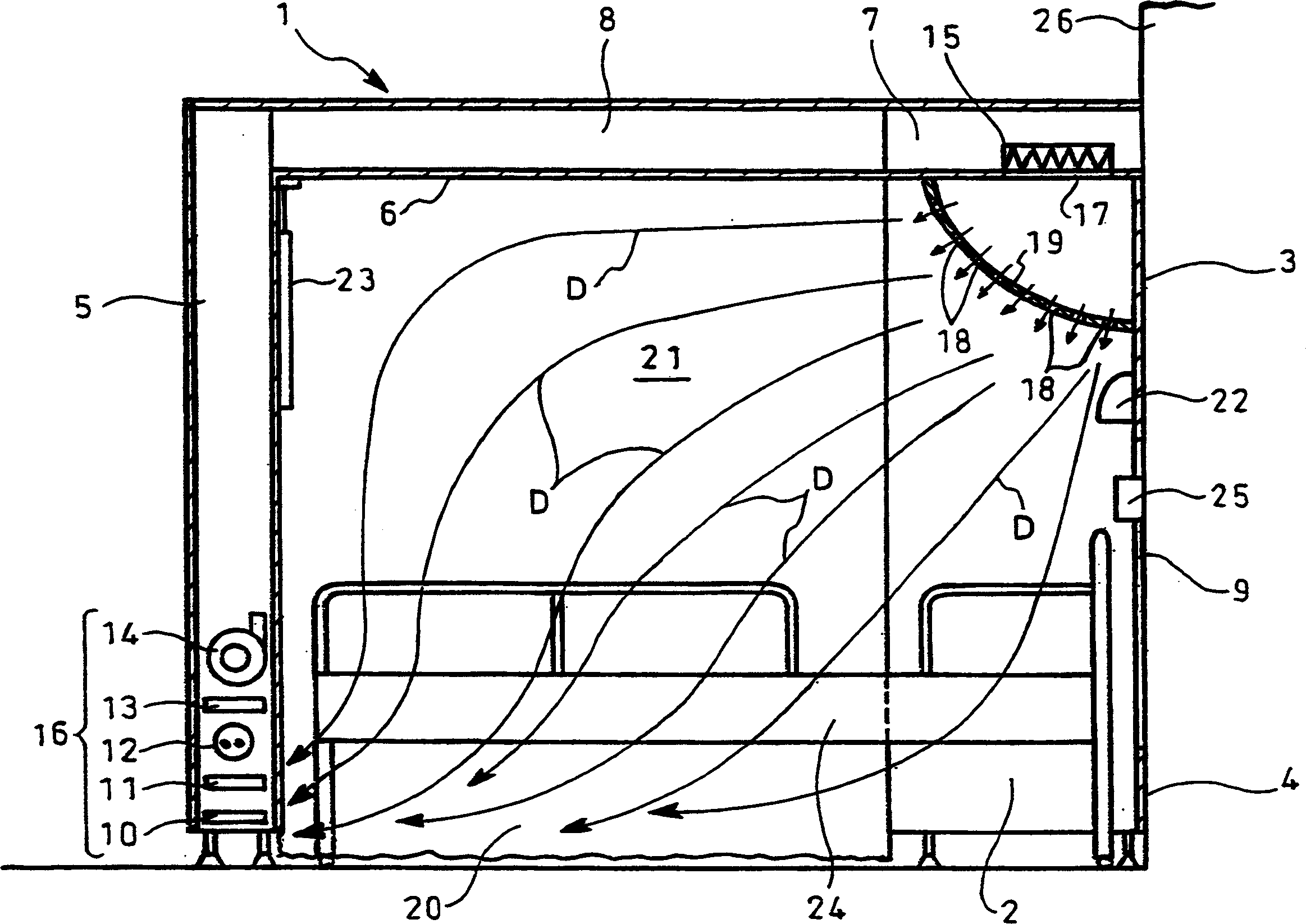
[0035] An embodiment of the present invention will be described with reference to the accompanying drawings. Figure 2-4 One embodiment of a clean room unit according to the invention is shown.

[0036] exist figure 2 with image 3 In , reference numeral 1 denotes a frame body of the sterile room unit. The frame body 1 includes a pair of opposite side panels 2, which are vertically arranged as front pillars; panel 3, fixed to the upper front end of the side panel 2 to be connected with the side panel 2; panel 4, fixed to the lower front end of the side panel 2, leaving The panel 3 is connected at a distance to the side panels 2; a hollow box-like chamber 5, vertically positioned and located between the side panels 2 when viewed from the rear, acts as a rear pillar, said box-like chamber 5 being wider than that between the side panels 2 A top plate 6 has an end, which is connected to the upper end of the side plate 2 at the side edge so as to extend horizontally to the box-s...


PUM


Abstract

The desinfection chamber consists of frame on floor and hanging curtain to enclose one inner space. The frame has an opened side part and the hanging curtain is used to open or close the opened side part selectively. The frame is provided with an airflow passage, and inside the airflow passage, there is air purifier extending from the foot part of patient to the head blowing canal to convey air via the frame. Via the blowing canal, purified air is blown into the desinfection chamber. The frame has one opening near the head of the patient, and via the opening, medical operating apparatus may be transferred into the desinfection chamber, and the frame is near the wall.

Description

technical field [0001] The invention relates to a clean room unit. Background technique [0002] Immunocompromised patients, for example, need to be isolated for several weeks in a sterile living space (sterile room) in a hospital to receive treatment. As such a therapeutic sterile living space, a sterile room unit is known. [0003] A conventional clean room unit is shown in Fig. 1, in which reference symbol a designates a frame body. The frame body a includes a box-shaped chamber b with ventilation equipment; one end of the beam c is fixed to the upper end of the box-shaped chamber b, and extends horizontally outward along the box-shaped chamber b; the beam d is arranged to be connected to the other end of the beam c connected. Beam e is arranged parallel to beam d so as to interconnect with the middle part of beam c; strut f is arranged perpendicularly to connect with the other end of beam c. [0004] A top plate (not shown) is fixed to the frame body a, and an openab...

Claims


Application Information

Patent Timeline
Patent Type & Authority Applications(China)
IPC IPC(8): A61G10/00
Inventor 饭岛和明谷知刚高木三郎
Owner SANKI ENG CO LTD
Why Eureka
Try Eureka