Pick-up head actuating unit for reversion

A technology of actuators and cameras, used in optical observation devices, vehicle components, transportation and packaging, etc.

Inactive Publication Date: 2004-11-17
SHANGHAI HUGONG AUTO ELECTRIC
View PDF0 Cites 13 Cited by
  • Summary
  • Abstract
  • Description
  • Claims
  • Application Information

AI Technical Summary

Problems solved by technology

[0004] In order to solve the technical problems existing in the use and installation of the existing reversing camera, the pre

Method used


Image

  • Pick-up head actuating unit for reversion
  • Pick-up head actuating unit for reversion
  • Pick-up head actuating unit for reversion

Examples


Embodiment Construction

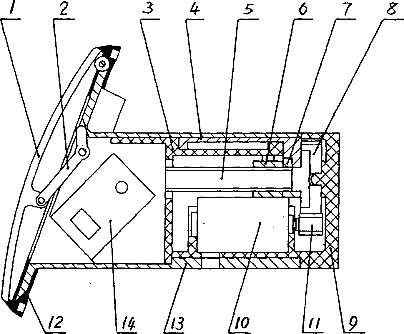
[0027] Such as figure 1 As shown, a reversing camera executive device consists of a front cover 1, a connecting rod 2, a frame 3, a positioning member 4, a screw rod 5, a nut 6, a connecting frame 7, a large gear 8, a base 9, a DC motor 10, and a pinion 11. Composed of a rubber ring 12, a housing 13 and a camera 14; where:

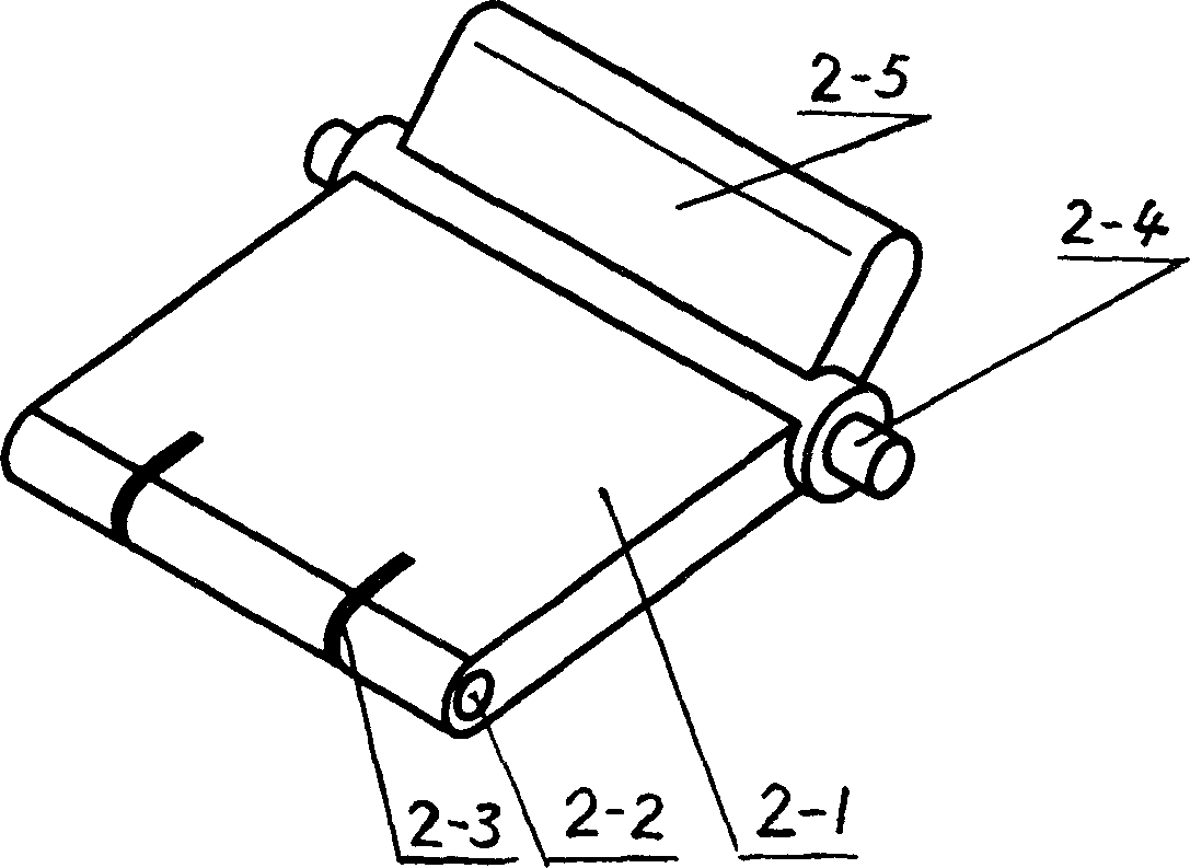
[0028] The connecting rod 2 is composed of a long arm and a short arm, one side of the long arm is connected to the front cover 1, and the connecting shaft of the long arm and the short arm is connected to the front end of the frame 3;

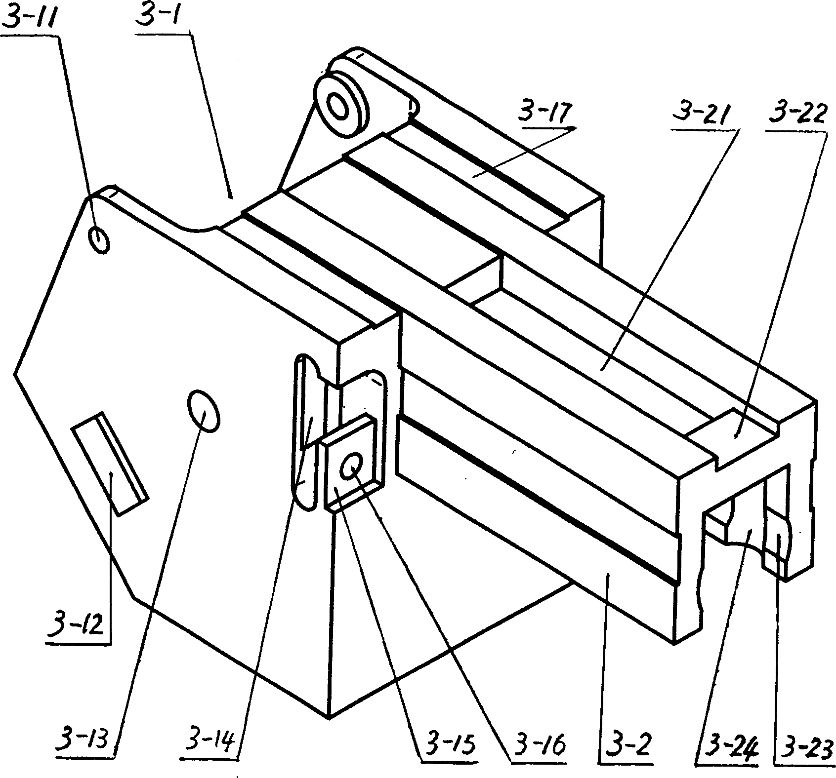
[0029] The front part of the frame 3 is a cavity, and its rear part protrudes from a ㄇ-shaped tail plate. There is a groove on the top plate of the tail plate, a gap higher than the groove is arranged at the top end of the top plate, and grooves are formed at the inner ends of the two wings of the tail plate;

[0030] The positioning piece 4 is placed in the gap above the top plate of the tail plate of the frame 3, and th...


PUM


Abstract

The invention provides a kind of astern running camera executing device, which is made up of front cover, link, frame, keeper, screw stem, nut, connecting bracket, a big gear, base, direct current engine, small gear, rubber ring, shell and camera; the frame is a main component, the other parts are connected with frame, the frame is embedded in the shell, and it can be moved parallel in the shell. The device structure is light and handy; the appearance is compact, which can be set in the back tank cover of the car. When astern running, the executing device can extend the camera in the car, it is convenient and safe.

Description

technical field [0001] The invention relates to auto parts, in particular to an actuator for a reversing camera. Background technique [0002] The current rapid development of the automobile industry can best reflect the level of high technology, such as the reversing monitoring system, from the initial voice prompts to radar ranging, and then developed to the camera display, that is, the reversing color camera is used to transmit the status of the rear of the car to On the monitor screen in front of the driver's seat for direct observation and judgment. The camera display is not affected by climate (such as night), venue (such as underground parking lot) and other environments, making reversing driving more convenient and safer. It is known as the third eye of the vehicle. [0003] The reversing camera monitoring system has developed rapidly in Europe, the United States, Japan and other major automobile countries, but only some large vehicles and cash transport vehicles ha...

Claims


Application Information

Patent Timeline
IPC IPC(8): B60R1/07
Inventor 江根福干上游施海星
Owner SHANGHAI HUGONG AUTO ELECTRIC
Why Eureka
Try Eureka