
Collimation measuring device

A technology for measuring devices and measuring racks, which is applied in the direction of measuring devices, optical devices, instruments, etc., and can solve problems such as noise, heat generation, and affecting machine operation

Inactive Publication Date: 2004-11-17
WUHAN UNIV OF TECH
View PDF2 Cites 15 Cited by
  • Summary
  • Abstract
  • Description
  • Claims
  • Application Information

AI Technical Summary

Problems solved by technology

[0003] When two rotating parts are connected by two rigid shafts, if there is a displacement deviation, it will also affect the operation of the machine, causing noise, heat and other undesirable phenomena

Method used


Image

  • Collimation measuring device
  • Collimation measuring device
  • Collimation measuring device

Examples


Embodiment Construction

[0108] The present invention will be further described below in conjunction with the accompanying drawings and embodiments.

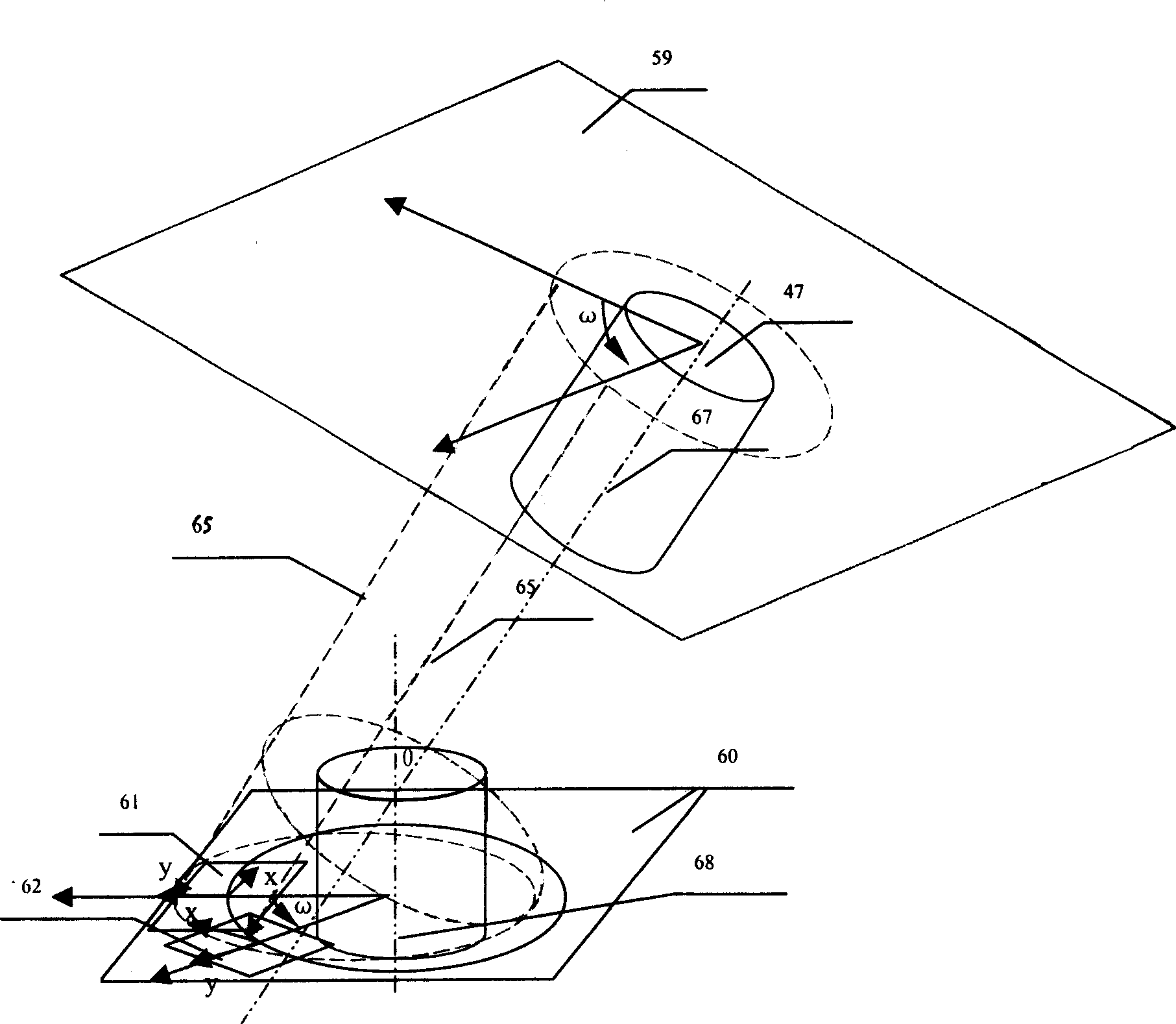
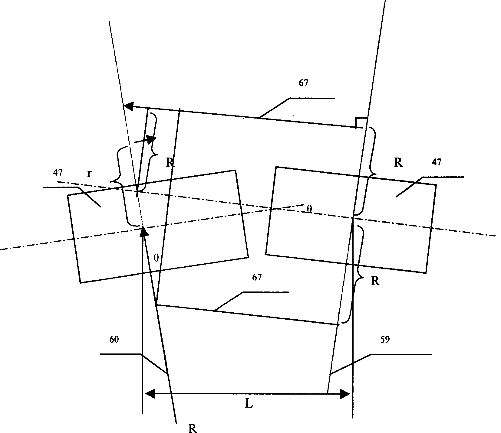
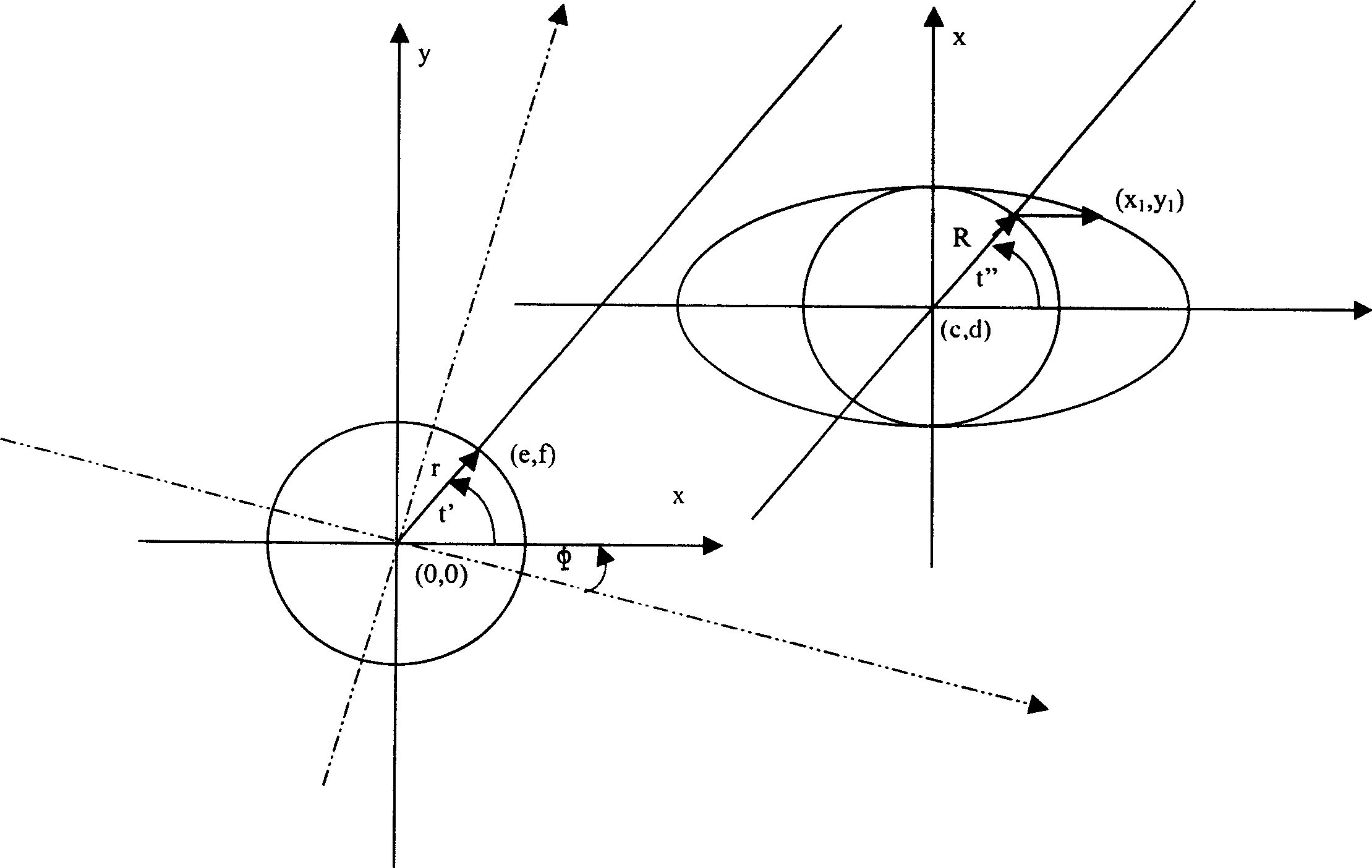
[0109] Such as Image 6 As shown, the collimation measurement device is composed of a transmitter 2, a receiver 3 and a measurement frame. The transmitter 2 and the receiver 3 are respectively installed on the L-shaped chassis 1 of the respective measurement frame, and their optical axes are parallel On the base of the L-shaped chassis 1, the light source 33 of the emitter, the small hole 37 of the light blocking plate 40 and the lens 58 are on the same optical axis in sequence, and the two-dimensional position optical measuring device 24 of the receiver 3 is on the same optical axis as the lens 58 Above, the two-dimensional position optical measuring device 24 of the receiver 3 is connected with the computer 36 by a signal line 68 . A convex lens 70 and a convex lens 71 are sequentially installed on the optical axis of the small hole 37 of the transmi...


PUM


Abstract

The invention refers to a kind of laser collimating device, especially refers to a kind of shift collimating measuring device for two hole axle measuring states. The character of the device lies in: it is made up of transmitter, receiver and measuring bracket. The transmitter and the receiver are set on the L type bottom bracket of itself measuring bracket, and the light axis is parallel to the base of the L type bottom bracket, and they rotates synchronously, the light source of the transmitter, the small hole of the light blocking board and the lens are on the same light axis in order, the two-dimension position optical measuring device of the receiver and the lends are on the same light axis. The two-dimension optical measuring device of the receiver is connected to the computer through a signal wire; the computer has a two-dimension coordinate displaying frame of off-set position of light spot. The invention can measure the relative shift between two holes or two axles, and it also can measure the off-set angle.

Description

technical field [0001] The invention relates to a laser collimation device, in particular to a relative offset collimation measuring device for measuring two conditions of a hole axis. Background technique [0002] At present, in the patented technical scheme reported in U.S. Patent US6040903 and German Patent DE3911307A1 literature, there are two two-dimensional displacement measurement sensors separated by a certain distance in a laser transmitter and a receiver, or many pairs of transmitters and receivers way, or use reflection to measure the offset of the two axes. When there are two displacement measurement sensors separated by a certain distance in a receiver, if the distance between the two displacement measurement sensors is very short, it is not suitable for the measurement of the shaft in a narrow space, the angular deviation is very small, and the two displacement measurement sensors need to be adjusted. In the manual, it is only mentioned to use the ellipse to c...

Claims


Application Information

Patent Timeline
IPC IPC(8): G01B11/27
Inventor 吕植勇陶德馨肖汉斌
Owner WUHAN UNIV OF TECH
Learn More