Directly-down backlight assembly

A backlight component, a direct type technology, applied in optics, nonlinear optics, instruments, etc., can solve the problems of light leakage, cold cathode tube 13 light source utilization rate reduction, light leakage and other problems

Active Publication Date: 2004-11-17
AU OPTRONICS CORP
View PDF0 Cites 6 Cited by
  • Summary
  • Abstract
  • Description
  • Claims
  • Application Information

AI Technical Summary

Problems solved by technology

In this way, due to the limitation of processing conditions, the large aperture of the through hole 15 will make it easy for light to

Method used


Image

  • Directly-down backlight assembly
  • Directly-down backlight assembly
  • Directly-down backlight assembly

Examples


Embodiment Construction

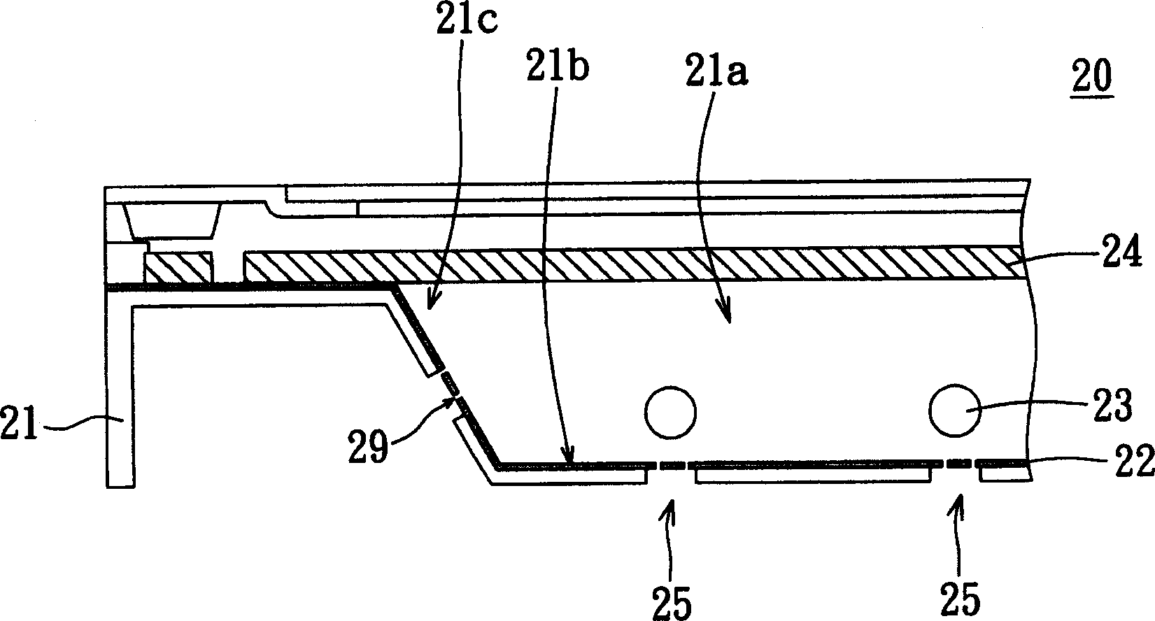
[0027] refer to figure 2 , figure 2 It is a partial sectional view showing a direct type backlight assembly according to a preferred embodiment of the present invention. figure 2 In the embodiment, the direct type backlight assembly 20 includes a bezel 21 , a reflecting sheet 22 and a plurality of light sources 23 . An accommodating groove 21 a is formed inside the frame 21 , and at least one through hole 25 is formed on the frame 21 through the accommodating groove 21 a to the outside. The shape of the perforation 25 can preferably be a long rectangle, and a plurality of perforations 25 are preferably arranged in parallel with each other, and are basically arranged relative to the light source 25. However, the present invention is not limited thereto, and perforations of other shapes and sizes can be made according to According to the actual effect or demand, it is adjusted accordingly to maintain the strength of the frame 21 within an acceptable range and achieve an opt...


PUM


Abstract

The invention is a kind of drop-off back component which can select the light source utilization rate and which has heat scattering effect. The component includes a light source, a frame and a reflecting plate. The light source is set in the frame; the frame includes at least a penetrated hole. The reflecting plate is set on the frame, which is used to mask the hole in the frame. The waste heat generated by the light source can be scattered out of the frame through the heat scattering hole of the reflecting plate.

Description

technical field [0001] The invention relates to a direct type backlight assembly, and in particular to a direct type backlight assembly with optimal light source utilization rate and heat dissipation effect. Background technique [0002] With the vigorous development of the liquid crystal display (Liquid Crystal Display, LCD) industry, the product application levels of various liquid crystal display panels continue to increase, and lighter and thinner products are constantly introduced. Since the liquid crystal display panel is a non-self-illuminating display panel, it must rely on light provided by a backlight module to perform a display function. [0003] Generally speaking, according to the position of the light source, the backlight assembly can be divided into two types: side-light type and direct-light type. The edge-lit backlight assembly places the light source on the side of the backlight assembly to reduce the thickness of the backlight assembly, so it is mostly u...

Claims


Application Information

Patent Timeline
IPC IPC(8): G02F1/1335G02F1/13357
Inventor 蔡宜轩
Owner AU OPTRONICS CORP
Why Eureka
Try Eureka