Combined type junction box

A junction box and combined technology, applied in the direction of electrical components, etc., can solve the problems of time-consuming and labor-intensive threading, inability to combine at will, inconvenient threading, etc., and achieve the effect of convenient wiring, standardization, and simple and reasonable structure

Active Publication Date: 2004-11-17
GUANGDONG FUTINA ELECTRICAL
View PDF0 Cites 4 Cited by
  • Summary
  • Abstract
  • Description
  • Claims
  • Application Information

AI Technical Summary

Problems solved by technology

It has the following defects: one is that the functions are fixed and cannot be combined at will; the other is that threading is inconvenient. When two or more junction boxes are arranged, one or more sides of the junction box must be pierced through, and threading is time-consuming and laborious.

Method used


Image

  • Combined type junction box
  • Combined type junction box
  • Combined type junction box

Examples


Embodiment Construction

[0025] The present invention will be described in further detail below in conjunction with the accompanying drawings and embodiments.

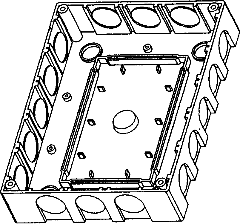
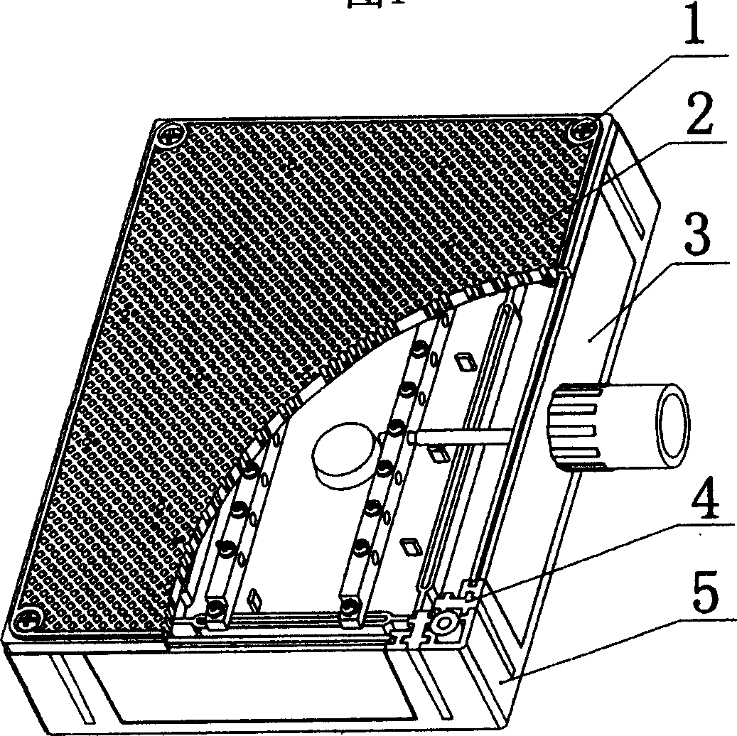
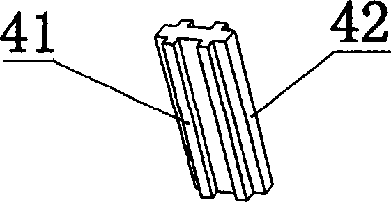
[0026] As shown in the figure, a combined junction box includes a cover 2 and a base 5 connected by screws 1 . The upper surface of the face cover 2 has mesh holes for self-tapping screw installation. A notch 51 and two connecting grooves 52 are respectively provided on the four side walls of the base. There is a groove 511 along the lip of the notch 51, the notch 51 is inserted with a flashboard 3, and the flashboard 3 has a shape corresponding to the notch and is inserted into the notch 511 from top to bottom to close the notch 51 (such as figure 2 ). The coupling groove 52 is arranged on both sides of the notch 51 , and the latch 4 is inserted into the coupling groove 52 from top to bottom. The latch 4 is composed of two identical, side-by-side, and integrated coupling parts 41 . One of the connecting parts 41 is located in the connecti...


PUM


Abstract

The invention discloses a kind of compound connection box. It includes a cover and the bottom which are connected by screw. On the four sides of the bottom, there sets an aperture and two connection slots on at least one side wall, there sets a concave slot along the lip of the aperture, the aperture has a plugging board, the shape of the plugging board is correspondent to the aperture and it is inserted into the concave slot to close the aperture, the connection slots are distributed at two sides of the aperture, there has a plug pin which is inserted from top down in the connection box, the plug pin is made up of two similar parallel and integral connection parts, one of them is in the connection slot, the second part extrudes out form the connection slot and matches with the another connection slot, the contacting side of the connection part and the connection slot are cross and localizes the plug pin along the thickness direction of the side wall, the plug pin and the board are sealed on the side wall. The structure in the invention is simple and reasonable, it is easy to be assembled, and the cost is low.

Description

(1) Technical field [0001] The invention discloses an electrical junction box, in particular to a combined junction box which can be assembled freely. (2) Background technology [0002] The base of the existing junction box (such as figure 1 ), is a monolithic structure. It has the following defects: one is that the functions are fixed and cannot be combined at will; the other is that threading is inconvenient. When two or more junction boxes are arranged, one side or multiple sides of the junction box must be pierced, and threading is time-consuming and laborious. (3) Contents of the invention [0003] The purpose of the present invention is to overcome the above disadvantages and propose a combined junction box that can be assembled at will. [0004] To achieve the above object, the present invention adopts the following technical solutions: [0005] A combined junction box, including a cover and a base connected by screws, at least one of the four side walls of the b...

Claims


Application Information

Patent Timeline
Patent Type & Authority Applications(China)
IPC IPC(8): H02G3/08
Inventor 万照勇
Owner GUANGDONG FUTINA ELECTRICAL
Why Eureka
Try Eureka