Unlock instant, AI-driven research and patent intelligence for your innovation.

Numerical control unit

A technology of digital control unit and frequency, which is applied in the direction of digital control, program control, computer control, etc., can solve the problems of reducing machining accuracy, difficult to judge normal cutting state and abnormal cutting state, etc.

Inactive Publication Date: 2004-12-01
FANUC LTD
View PDF2 Cites 25 Cited by
  • Summary
  • Abstract
  • Description
  • Claims
  • Application Information

AI Technical Summary

Problems solved by technology

In such a low-wear state, when cutting abnormalities occur, the temporarily increased load acting on the spindle or feed shaft will rarely reach the predetermined reference value for preventing tool breakage, therefore, it is difficult to detect locally Cutting abnormalities that reduce machining accuracy
In other words, the continuous use of the tool leads to the development of wear and the gradual increase of the cutting resistance acting on the tool, so that if the judgment standard is fixed, it is difficult to judge the normal cutting state by the magnitude of the load acting on the spindle or feed shaft and abnormal cutting conditions

Method used


Image

  • Numerical control unit
  • Numerical control unit
  • Numerical control unit

Examples


Embodiment Construction

[0020] Hereinafter, embodiments of the present invention will be described in detail with reference to the accompanying drawings. In these figures, the same or similar elements are denoted by common symbols.

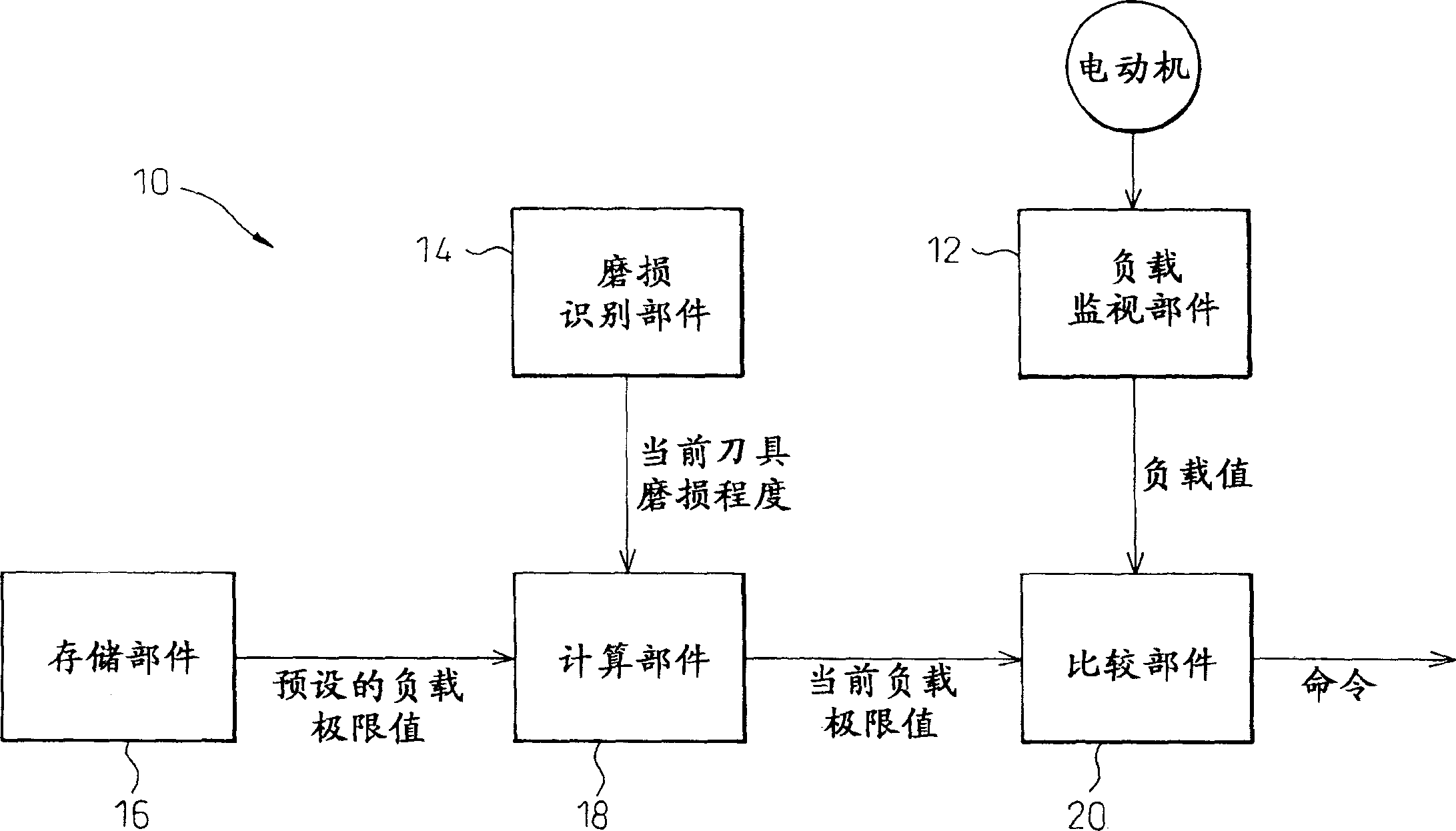
[0021] With reference to the accompanying drawings, figure 1 A block diagram representing the basic principle of a digital control unit according to the invention. The digital control unit 10 according to the present invention comprises a load monitoring part 12 for monitoring the load on the motor, a wear recognition part 14 for identifying the current degree of tool wear, for storing multiple values ​​respectively corresponding to predetermined various degrees of tool wear. A storage unit 16 for a predetermined limit load value, a calculation unit for calculating a current limit load value corresponding to the current degree of tool wear identified in the wear identification unit 14 based on a plurality of predetermined limit load values ​​stored in the storage unit 1...


PUM


Abstract

A numerical control unit having a load monitoring function for monitoring a load on a tool drive source during a machining operation. The numerical control unit includes a load monitoring section for monitoring the load on an electric motor; a wear recognizing section for recognizing the current extent of tool wear; a storing section for storing a plurality of preset limit load values corresponding individually to predetermined various extents of tool wear; a calculating section for calculating the current limit load value corresponding to the current extent of tool wear recognized in the wear recognizing section, based on the plurality of preset limit load values stored in the storing section; and a comparing section for comparing the load on the electric motor, monitored in the load monitoring section, to the current limit load value calculated in the calculating section, and for judging on the abnormality of the load. The wear recognizing section recognizes the current extent of tool wear by using one parameter selected from a group consisting of the number of times of use of a tool, the duration of cutting by a tool, the distance of cutting by a tool and the number of times of execution of machining program. The load monitoring section monitors at least one of maximum value, average value and minimum value of the load in a certain procedure of a machining program.

Description

technical field [0001] The present invention relates generally to numerical control units for machine tools, and more particularly to numerical control units having a load monitoring function for monitoring the load on a tool drive source during machining operations. Background technique [0002] In the field of machine tools, it has been proposed to detect the cutting resistance acting on the machine tool as the load applied to the spindle for rotating the tool or the feed shaft for feeding the tool during machining operations, and according to the magnitude of the load Various methods of controlling the operation of the spindle or feed axis in order to prevent tool breakage. Generally speaking, due to continuous use, the cutting edge of the knife will wear down and eventually will break off. In the event that the edge of the tool is worn, the load applied to the respective tool spindle or tool feed axis will increase during cutting of the workpiece by the tool. Therefore...

Claims


Application Information

Patent Timeline
Patent Type & Authority Applications(China)
IPC IPC(8): B23Q17/09G05B19/18G05B19/4065
CPCB23Q17/09G05B2219/50328G05B19/4065B23Q17/0961
Inventor 井上道也石井一
Owner FANUC LTD