Embroidery machine

An embroidery machine and cantilever technology, which is applied to embroidery machines, embroidery machine mechanisms, sewing machine components, etc., can solve the problems of not being able to maintain it for a long time, the elasticity of the spring plate is easy to drop, and the cost is increased.

Inactive Publication Date: 2010-05-05
TOKAI IND SEWING MACH CO LTD
View PDF4 Cites 0 Cited by
  • Summary
  • Abstract
  • Description
  • Claims
  • Application Information

AI Technical Summary

Problems solved by technology

The structure of the above-mentioned ① has the following problem, that is, when each spring plate is deformed due to the butt joint with the joint release means, due to the torsional force, the elastic force of the spring due to long-term use is weakened.
The disadvantage is that even in a structure that is not subject to such torsion, the spring force of the spring plate is likely to drop, and it cannot be reliably maintained for a long time.
If the cantilever cannot be held in a certain posture, there will be a serious problem that other parts such as the cantilever will be damaged due to the color change action.
In addition, the disadvantage of the structure of ② above is that as a structure for sliding the sliding member, three connecting ring parts are used in total. Therefore, due to the gap between the connecting parts of each connecting ring, not only is it easy to generate movement errors, but also the cost is increased.

Method used


Image

  • Embroidery machine
  • Embroidery machine
  • Embroidery machine

Examples


Embodiment Construction

[0012] An embodiment of the present invention will be described below with reference to the accompanying drawings.

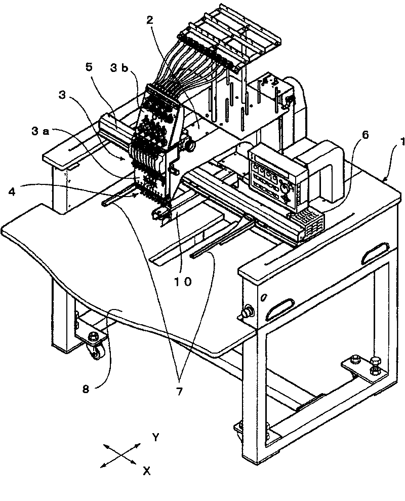
[0013] figure 1 It is a perspective view showing the appearance of the single-head embroidery machine of this embodiment. figure 1 Among them, the machine arm 2 is set on the machine table 1 constituting the embroidery machine body. The machine arm 2 is erected from the rear end of the approximate center of the machine table 1, and the front end is extended toward the front (the side where the operator is located) and is arranged to extend forward and backward (Y direction). On the top, the head 3 is supported so as to be slidable in both left and right directions (X direction). The machine head 3 is composed of a support body 3a and a yarn adjustment table 3b. The support body 3a is located below the machine head 3 and supports a plurality of needle bars 4 (nine in the illustrated example), and the yarn adjustment table 3b is installed on the machine head 3. ...


PUM


Abstract

An embroidering machine is capable of maintaining an unusing balance on a top dead center surely. An embroidering machine comprises: a holding body supporting plural balances(15) and plural needle rods; a color changing device(40) driving one selected from the balances(15) and the needle rods selectively; and a balance maintaining device permitting driving of the selected balance and maintaining the balance not selected on proper position. The balance maintaining device comprises: a correspondent groove(16c) formed on each balance; a lock lever(18) corresponding to each balance, being capableof shaking and inserting a tip(18b) into the correspondent groove(16c) to maintain the balance on proper position; a spring member(20) supporting the lock lever(18) in a direction that the tip(18b) isinserted into the correspondent groove(16c); and a maintenance release device(18c) shaking the corresponded lock lever(18) to extricate the tip(18b) from the correspondent groove(16c).

Description

technical field [0001] The present invention relates to an embroidery machine for selectively using a plurality of needle sticks to form embroidery patterns of various colors on embroidery cloth, etc., more particularly, having a cantilever for holding a cantilever not in use in a prescribed posture Hold device for embroidery machine. Background technique [0002] [Patent Document 1] JP-A-2002-235271 [0003] In the above-mentioned Patent Document 1, there is a description about an embroidery machine for selectively using a plurality of needle bars to form embroidery patterns of various colors on embroidery cloth or the like. In order to keep the unused (non-selected) cantilever at The structure of the top dead center position is ① directly pressed by a spring plate, and ② a structure in which the end of the sliding member capable of advancing and retreating enters and exits the coupling groove provided on the boss of the boom. The structure of the above-mentioned ① has th...

Claims


Application Information

Patent Timeline
Patent Type & Authority Patents(China)
IPC IPC(8): D05C11/16D05B55/16D05B49/00D05C3/00
CPCD05C3/02
Inventor 田岛郁夫村濑爱介
Owner TOKAI IND SEWING MACH CO LTD
Why Eureka
Try Eureka