
Double-coated optical fiber

An optical fiber and double-layer technology, which is applied in the field of double-layer coated optical fiber and its coating layer peeling force, can solve the problem of no outer diameter of the main coating layer, etc.

Inactive Publication Date: 2004-12-01
SAMSUNG ELECTRONICS CO LTD
View PDF0 Cites 0 Cited by
  • Summary
  • Abstract
  • Description
  • Claims
  • Application Information

AI Technical Summary

Problems solved by technology

Also, there is no clear regulation for the outer diameter of the main coating layer (test standards: IEC60793-2, GR-20-CORE, TIA / EIA-492c000, etc.)

Method used


Image

  • Double-coated optical fiber
  • Double-coated optical fiber
  • Double-coated optical fiber

Examples


Embodiment Construction

[0016] Preferred embodiments of the present invention will be described below with reference to the accompanying drawings. The skilled person will understand that the claimed invention is not limited to the embodiments shown in the drawings. For example, those skilled in the art can make many improvements within the spirit and scope of the present invention. For clarity and simplicity, well-known functions or constructions are not described in detail since they would obscure the invention in unnecessary detail.

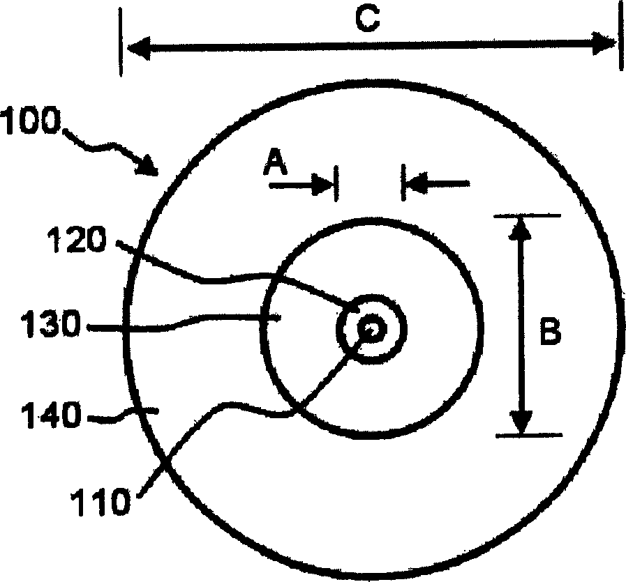
[0017] figure 1 It is a schematic cross-sectional view of a double-coated optical fiber according to a preferred embodiment of the present invention. refer to figure 1 , the optical fiber 100 includes a core 110 , a cladding 120 , a primary coating 130 and a secondary coating 140 .

[0018] All of the aforementioned components are generally arranged around a common central point. The core 110 is disposed at the center of the optical fiber 100 . Thus, the core ac...


PUM

PropertyMeasurementUnit
thicknessaaaaaaaaaa
thicknessaaaaaaaaaa
thicknessaaaaaaaaaa

Abstract

A double-coated optical fiber and method includes providing a core that serves as a light transmission medium. A cladding surrounds the core and has a smaller reflective index than the core. A primary coating layer is formed of a UV-cured polymer around the clad, and a secondary coating layer is formed of a UV-cured polymer around the primary coating layer, to a thickness ranging from about 22 to 37.5 mum in order to obtain a coating strip force ranging from about 1.0 to 1.63 N and a dynamic stress corrosion parameter ranging from 20 to 29. The primary and secondary coating layers can be formed by a wet on wet or wet on dry process.

Description

technical field [0001] The present invention generally relates to an optical fiber. More specifically, the present invention relates to a double-coated optical fiber and its coating peel force. Background technique [0002] In general, optical fibers include a core that provides a medium for transmission of light and a cladding surrounding the core to confine light within the core. A coating surrounds the cladding and serves to protect the interior of the fiber from the external environment. [0003] The coating is a very important component for determining the physical fiber properties such as bend, chemical resistance and mechanical strength. In order to measure the mechanical properties of the optical fiber, it is known in the art to perform a dynamic fatigue test and a coating layer peeling test to evaluate the quality of the optical fiber. [0004] Because optical fibers undergo physical changes due to external factors when they are used in real-world applications, d...

Claims


Application Information

Patent Timeline
Patent Type & Authority Applications(China)
IPC IPC(8): G02B6/00G02B6/02G02B6/245
CPCG02B6/245G02B6/02395G02B6/02G02B6/00
Inventor 金永锡吴成国李载昊
Owner SAMSUNG ELECTRONICS CO LTD
Learn More