

Turntable drive device
A technology of driving device and rotary table, which is applied in the direction of machines/stands, TVs, color TVs, etc. It can solve problems such as unsmooth movements, difficult to adjust screw tightening torque, and large circuit load, and achieve the effect of preventing damage
- Summary
- Abstract
- Description
- Claims
- Application Information
AI Technical Summary
Problems solved by technology
Method used
Image

Examples
Embodiment Construction
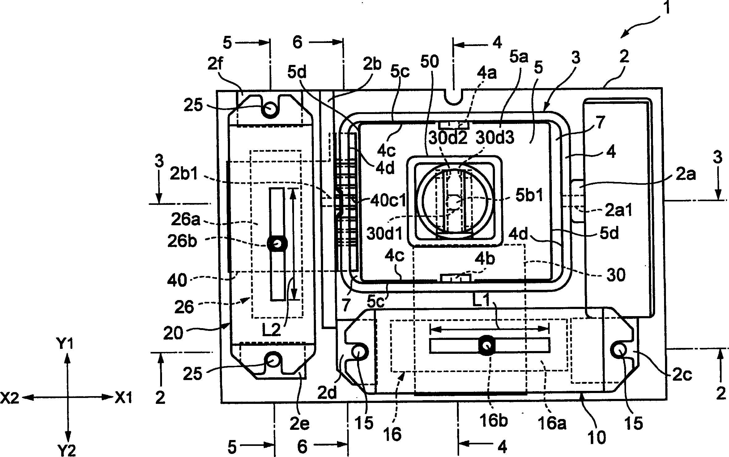
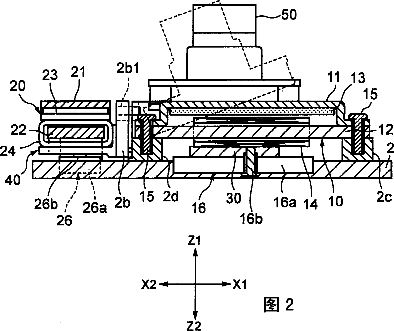
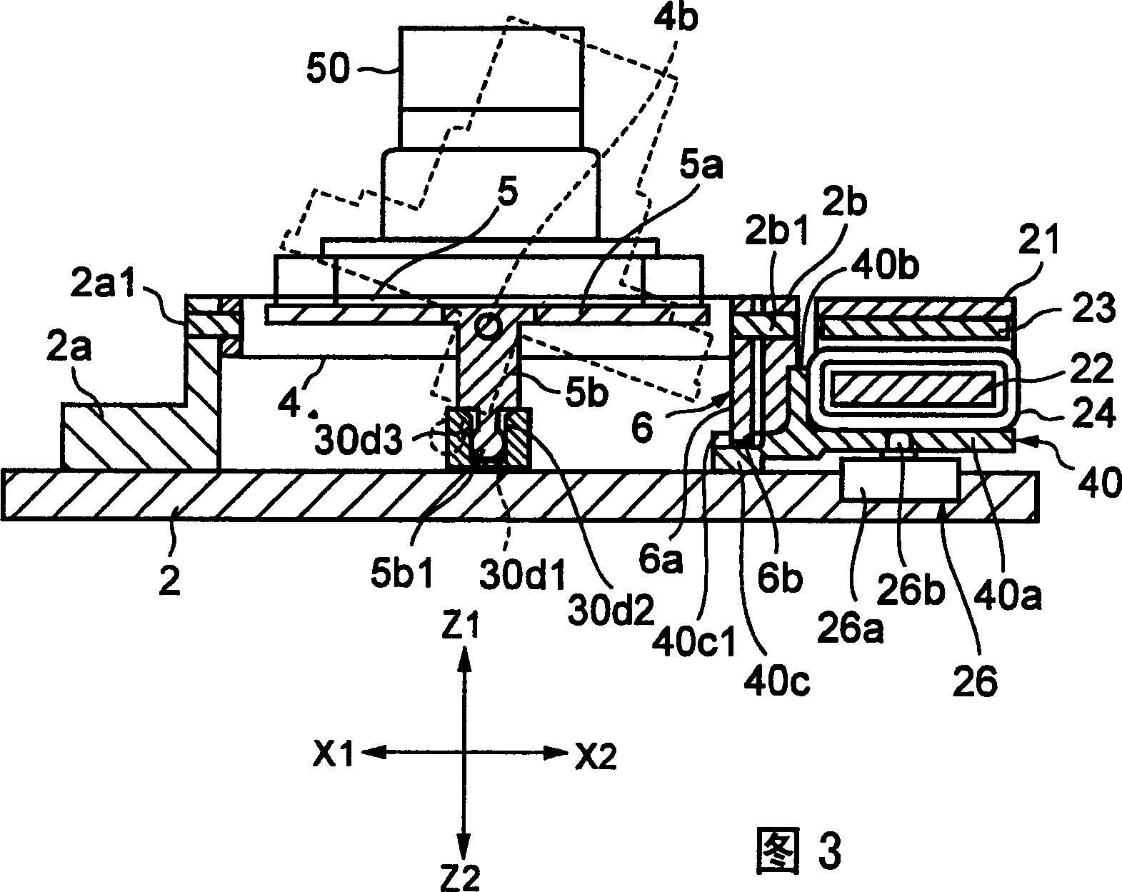
[0050] figure 1 It is a perspective view of the entire turntable driving device viewed from the front as the first embodiment of the present invention, and FIG. figure 1 The cross-sectional view when the 2-2 line is cut, Figure 3 is according to figure 1 The sectional view when the 3-3 line is cut, Figure 4 yes press figure 1 The sectional view when the 4-4 line is cut, Figure 5 yes press figure 1 The sectional view when the 5-5 line is cut, Figure 6 yes press figure 1 The cross-sectional view when the 6-6 line is cut, and Fig. 7 is a functional block diagram, Figure 8 is a flowchart.
[0051] The turntable driving device 1 of the first embodiment can be used, for example, as a video camera equipped with the camera part 50 and used as a door phone for residential use to identify visitors, or a video phone connected to a computer and used via an Internet line. Use a camera. In addition, in the following embodiments, the Z direction corresponds to the up-down direct...
PUM
 Abstract
Description
Claims
Application Information