Eureka AIR delivers breakthrough ideas for toughest innovation challenges, trusted by R&D personnel around the world.

Rotor position determination in a switched reluctance machine

A rotor position and rotor technology, applied in the direction of DC motor speed/torque control, electronic commutator, AC motor control, etc.

Inactive Publication Date: 2004-12-01
NIDEC SR DRIVES
View PDF4 Cites 21 Cited by
  • Summary
  • Abstract
  • Description
  • Claims
  • Application Information

AI Technical Summary

Problems solved by technology

[0010]Having to store a 2D array of motor data in order to operate without a position sensor is an obvious disadvantage

Method used


Image

  • Rotor position determination in a switched reluctance machine
  • Rotor position determination in a switched reluctance machine
  • Rotor position determination in a switched reluctance machine

Examples


Embodiment Construction

[0034] The exemplary embodiment to be described employs a 2-phase switched reluctance drive in motoring mode, but any number of phases could be used and the drive could be in motoring or generating mode.

[0035] Figure 5 A system is shown for implementing the invention, in which one form of the invention is embodied. Wherein, a power converter 13 is provided for controlling the switched reluctance motor, and the above power converter 13 is generally the same as the power converter shown in FIG. 1 . What controls the converter 13 is a controller 42. In this embodiment, the above-mentioned controller 42 includes: a processor, especially a digital signal processor 44, such as one of the Analog Devices2181 series; and related programs and data memory 46. Alternative embodiments may include a microprocessor or other form of programmable device, as is well known in the art. The processor operates in conventional manner in accordance with the program code stored in memory 46 to c...


PUM


Abstract

A switched reluctance drive is controlled without using a physical rotor position detector. The control method causes current to flow continuously in a single winding when the rotor is turning and detects position by finding either the peak of the current waveform or some other feature which can be uniquely related to the position of the rotor.

Description

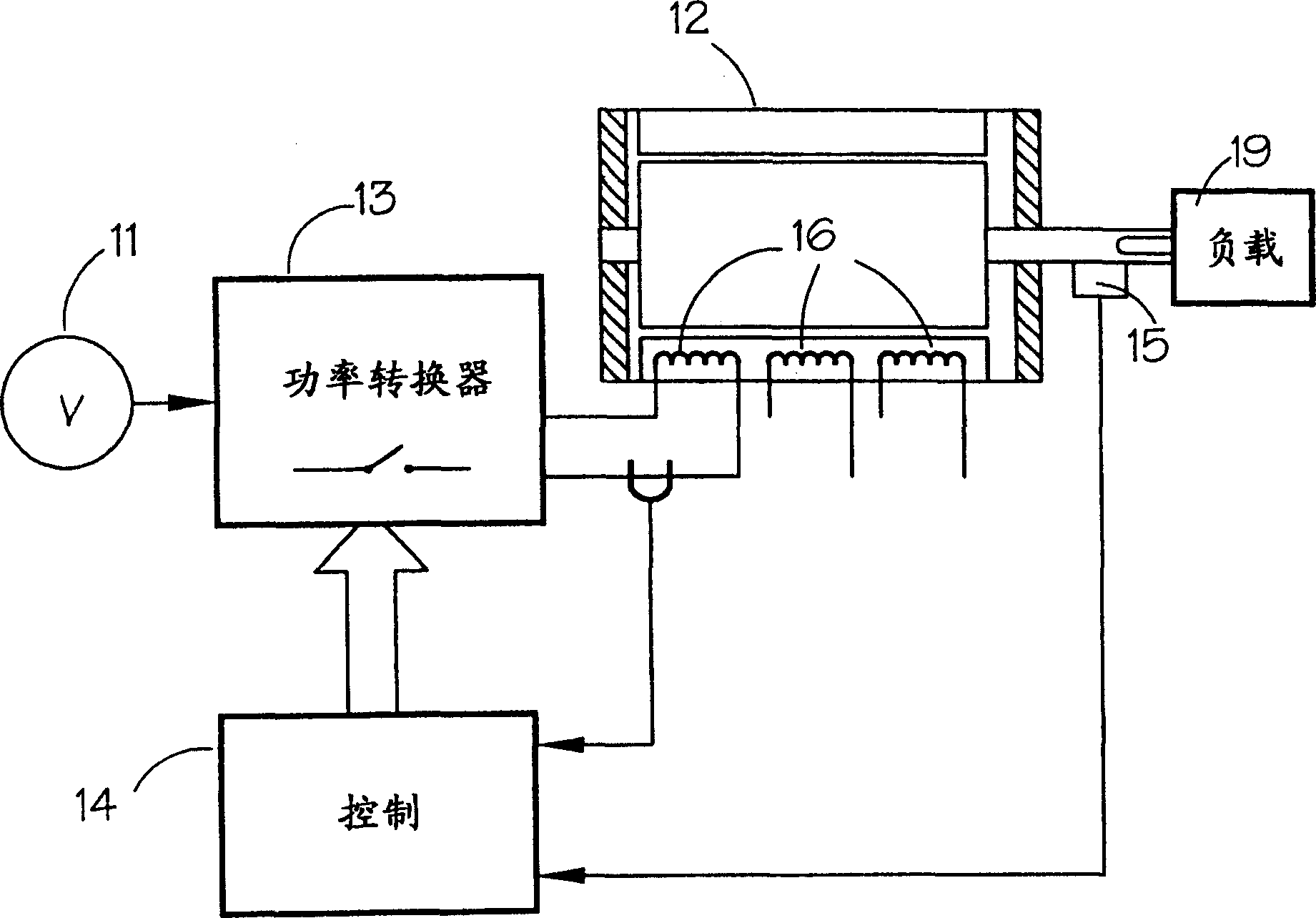
technical field [0001] The present invention relates to sensorless rotor position determination in reluctance machines, especially but not exclusively, in switched reluctance machines. Background technique [0002] The control and operation of switched reluctance motors in general was described in a paper "The Characteristics, Design and Applications of Switched Reluctance Motors and Drives", which is hereby incorporated by reference. In that paper, the "chopper" and "single-pulse" modes of excitation for switched reluctance motors are described for operation of the motor at low and high speeds, respectively. [0003] A typical prior art drive is schematically shown in FIG. 1 . This includes a direct current (DC) power source 11, which may be a battery, or a rectified and filtered alternating current (AC) power source. The DC voltage provided by the power supply 11 is switched across the phase winding 16 of the electric motor 12 by a power converter 13 under the control o...

Claims


Application Information

Patent Timeline
Patent Type & Authority Applications(China)
IPC IPC(8): G01D5/20H02P1/46H02P6/18H02P7/00H02P25/08
CPCG01D5/2013H02P6/185H02P25/083H02P25/089H04M2250/06H04M1/72403H04M1/72469
Inventor H·J·斯莱特J·D·A·钱伯斯
Owner NIDEC SR DRIVES
Why Eureka
Eureka Blog
Learn More