Eureka AIR delivers breakthrough ideas for toughest innovation challenges, trusted by R&D personnel around the world.

Hydraulic central gyrorotor

A rotary and central technology, applied in fluid pressure actuating devices, lifting devices, lifting frames, etc., can solve problems such as inconvenient operation and maintenance, short service life of pipelines, small rotation angle, etc.

Inactive Publication Date: 2005-01-12
JIANGSU CHANGLING HYDRAULIC CO LTD
View PDF0 Cites 2 Cited by
  • Summary
  • Abstract
  • Description
  • Claims
  • Application Information

AI Technical Summary

Problems solved by technology

[0002] Conventional hydraulic excavators, cranes, etc., the rotation of the upper and lower parts is driven by a single-tube oil cylinder, and the rotation angle is generally 50-80°. The rotation angle is small, the operation and maintenance are inconvenient, the pipeline is prone to interference, and the service life of the pipeline short

Method used


Image

  • Hydraulic central gyrorotor
  • Hydraulic central gyrorotor
  • Hydraulic central gyrorotor

Examples


Embodiment Construction

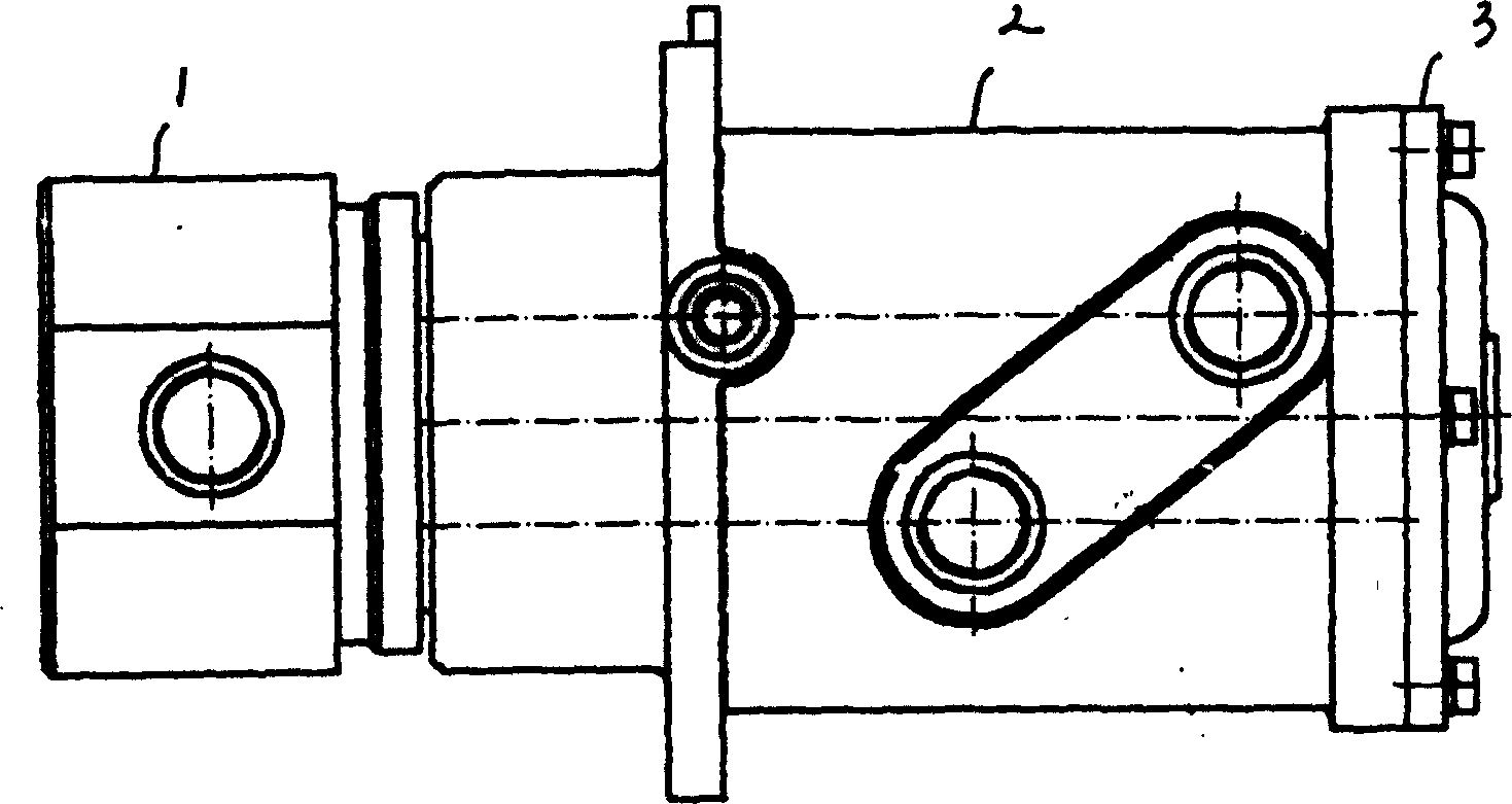
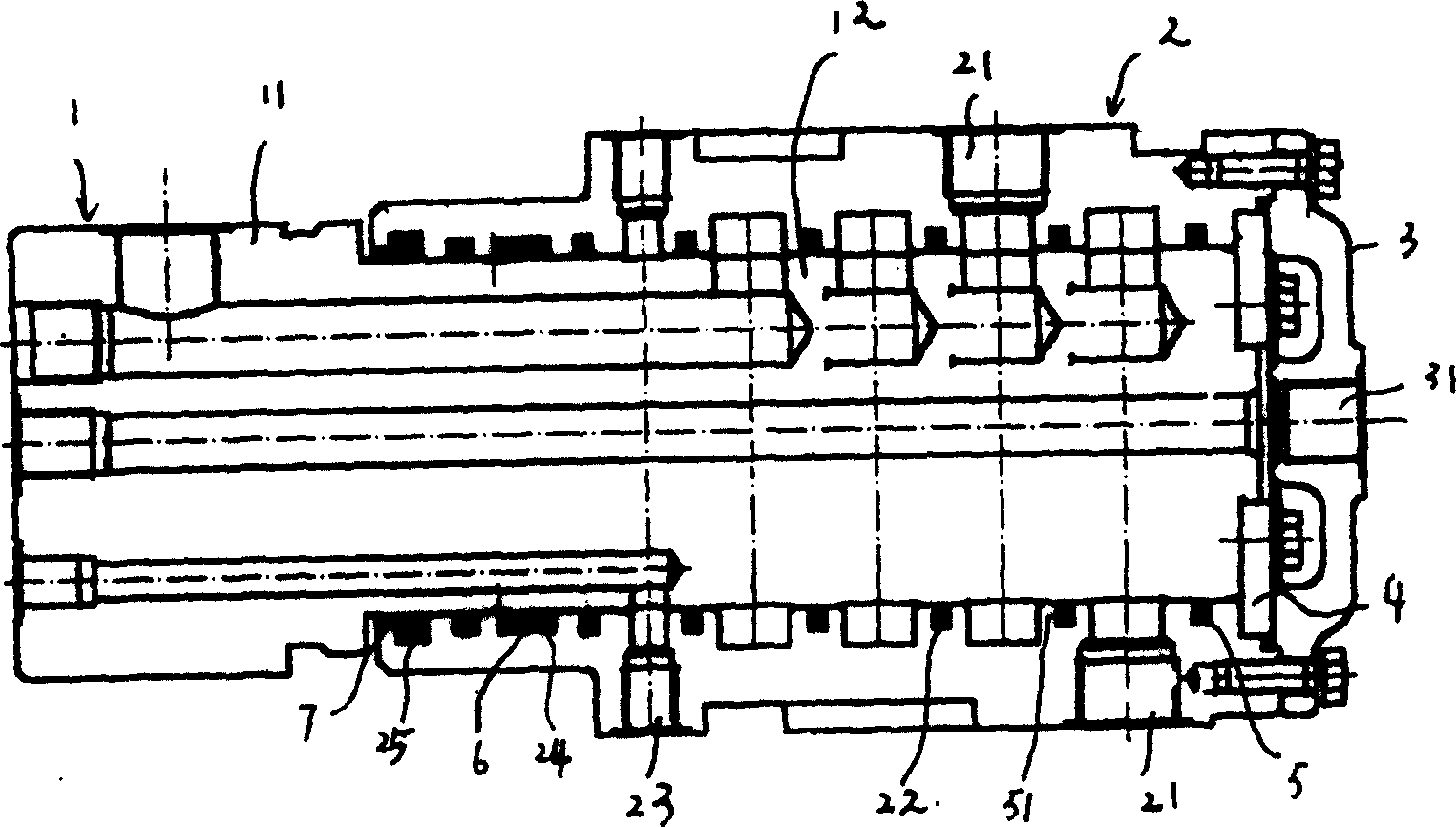
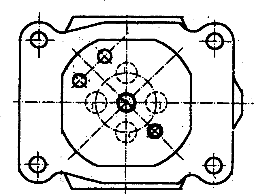
[0023] Such as Figure 1~4 , The present invention is a hydraulic central slewing body, which is mainly composed of a slewing body 2, a rotating shaft 1, an end cover 3, a positioning cover 4, a seal 5, a support ring 6 and a dust ring 7. The rotary shaft 1 is composed of a front pipeline connecting section 11 and a rear mounting section 12. The rear mounting section 12 of the rotary shaft 1 is inserted into the revolving body 2, the front pipeline connecting section 11 is placed at the outer front end of the revolving body 2, and the end cover 3 is placed at the outer rear end of the revolving body 2. The positioning cover 4 is embedded in the rear end of the rotating body 2 and connected with the rear end of the rotating shaft 1.

[0024] Such as Figure 5-14 , The front pipeline connecting section 11 and the rear mounting section 12 of the rotary shaft 1 are provided with a plurality of main oil passage holes 13 in the axial direction, and a plurality of main oil ports 111 and 1...


PUM


Abstract

The hydraulic central revolver is composed of revolver, the rotor, the sealing apparatus and shield. The rotor is installed in the revolver. The front pipe is in the front end of the revolver. The shield is in the back endo f the revolver. At axial direction the oilway main hole, low pressure oilway hole, oil leakage hole is opened on the rotor. At the radial direction, the olway main hole, low pressure oil hole is opened on the revolve, the oilway main hole, oilway main mouth are connected, low pressure oilway hole and low pressure oil hole are connected. The oil leakage hole is connected with the oil leakage mouth. The sealing apparatus is fixed in the inner wall of the revolver to achieve the rotation in 360 deg. For maintenance convenience.

Description

Technical field: [0001] The invention relates to a hydraulic central slewing body. Mainly used in the entire hydraulic system of excavators, cranes, graders, tower cranes and other machinery. It is the hydraulic pipeline that connects the fixed and rotating parts of the entire hydraulic system. Background technique: [0002] Conventional hydraulic excavators, cranes, etc., the upper and lower parts of the rotation are drawn by single-cylinder cylinders. The rotation angle is generally 50-80°, the rotation angle is small, the operation and maintenance are inconvenient, the pipeline is prone to interference, and the pipeline service life short. Summary of the invention: [0003] The purpose of the present invention is to overcome the above-mentioned shortcomings and provide a hydraulic central slewing body with large slewing angle, convenient operation and maintenance, and no interference of pipelines. [0004] The purpose of the present invention is achieved as follows: a hydraul...

Claims


Application Information

Patent Timeline
IPC IPC(8): B66C13/20B66F7/20E02B3/28E02F3/85F15B15/02F15B15/20F16J15/16
Inventor 邬逵清张爱军刘雄杰张晓平夏泽民卢海罗银娟
Owner JIANGSU CHANGLING HYDRAULIC CO LTD
Why Eureka
Eureka Blog
Learn More