Dynamic stacking memory management method for preventing buffering area from overflow attacking

A memory management and stack technology, applied in memory systems, electrical digital data processing, digital data processing components, etc., can solve problems such as buffer overflow attacks, and achieve the effect of preventing stack buffer overflows

Inactive Publication Date: 2005-01-12
NANJING UNIV
View PDF0 Cites 27 Cited by
  • Summary
  • Abstract
  • Description
  • Claims
  • Application Information

AI Technical Summary

Problems solved by technology

If when the function returns, it is found that the value of the canary has been changed, it proves that someone may be trying to perform a buffer overflow attack

Method used


Image

  • Dynamic stacking memory management method for preventing buffering area from overflow attacking
  • Dynamic stacking memory management method for preventing buffering area from overflow attacking
  • Dynamic stacking memory management method for preventing buffering area from overflow attacking

Examples


Embodiment Construction

[0022] The above is the basic principle of the present invention, which can be implemented in multiple ways. For example, special memory devices (including software devices and hardware devices) can be used to implement. It can also be implemented using special computer systems. It is also possible to rewrite the compiler to generate an object program with the above functions. In short, various implementations within the spirit of the principles should be included. An example is given below to specifically illustrate the execution process of the program using this method.

[0023] I. Execution of normal procedures

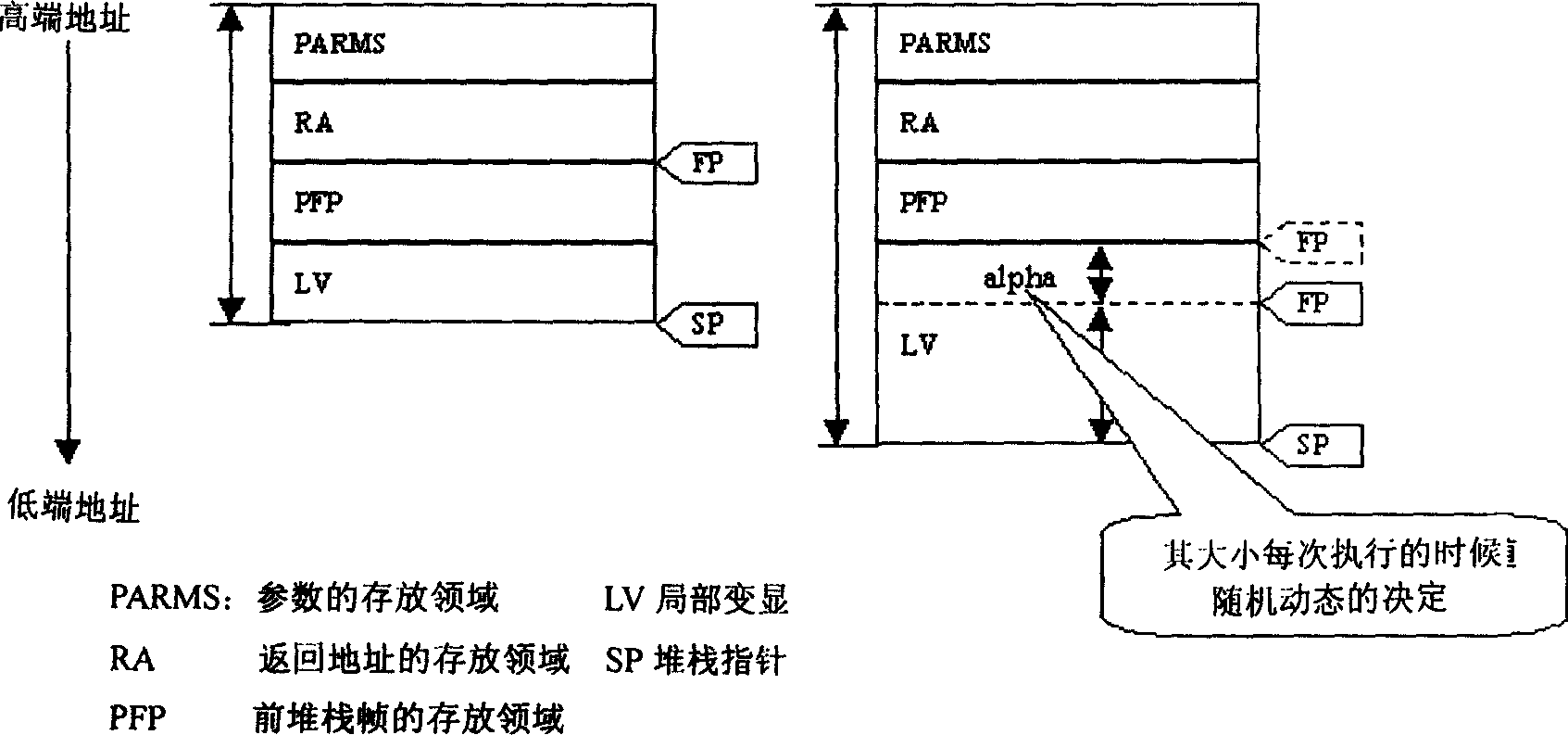
[0024] call parameters

return address

previous stack frame pointer

local variable

[0025] We use SP to represent the stack pointer, FP to represent the frame pointer, and RA to represent the return address.

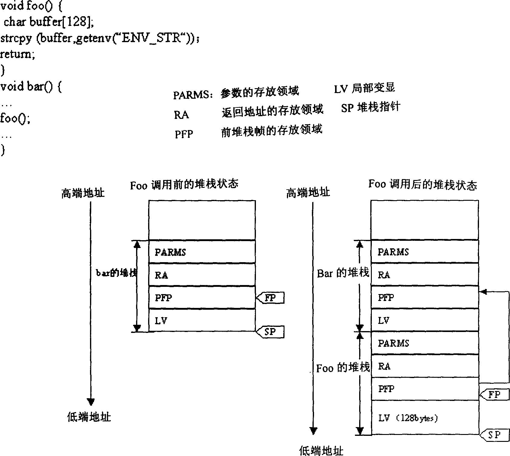
[0026] ● before the function foo is called

[0027] Before the function foo is called, the stack pointer (SP) poin...


PUM


Abstract

Since relative position between return address and local variable is changed in dynamic random, return address is not possible to be rewritten so as to prevent attacking computer by using buffer flood. The invention includes following claim of rights: method of dynamic stack memory management including object program, compiler, memory device and computer system, which possesses characters of the method.

Description

1. Technical field [0001] The invention relates to a dynamic stack memory management method, and preventing buffer overflow is a common method for attacking computer systems. The invention proposes a dynamic stack memory management method, which can effectively prevent buffer overflow attacks. 2. Technical background [0002] A buffer is a place where data is stored in computer memory when a program is running. When a program tries to write a piece of data into a certain memory buffer, if the length of the data exceeds the length of the buffer, a buffer overflow occurs. Assailants can exploit this weakness to attack computers (see [1] E. Spafford. The Internet Worm Program: Analysis. Computer Communication Review, January 1989). The attacker writes a string that exceeds the length of the buffer into the buffer. Because the super-long character string written covers the adjacent storage unit, it often leads to two kinds of results. One is to cause the program to fail to r...

Claims


Application Information

Patent Timeline
Patent Type & Authority Applications(China)
IPC IPC(8): G06F1/00G06F9/00
CPCG06F21/52
Inventor 龚如宾潘金贵
Owner NANJING UNIV
Why Eureka
Try Eureka